
User's Manual

124
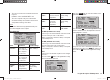
Program description: Telemetry menu
determined separately for each direction by the values
entered in these tw
o lines.
TAIL TYPE
The following model types are also available in the “Tail”
line of the “Basic settings” menu (see page 58), and
should normally be set up at that point. If you have done
this, you should always leave the TAIL TYPE at NOR-
MAL.
However, if you prefer to use the receiver’s integral
mixers, you can select the pre-set mixer function for the
corresponding model type:
NORMAL•
This setting corresponds to the classic aircraft type
with tail-mounted stabiliser panels and separate rud-
der and elevator. No mixer function is required for this
model type.
V-TAIL•
For this model type the control functions elevator and
rudder are linked together in such a way that each of
the two control surfaces - actuated by a separate ser-
vos - carries out superimposed elevator and rudder
functions.
The servos are usually connected to the receiver as
follows:
OUTPUT CH 3: left V-tail servo
OUTPUT CH 4: right V-tail servo
If you fi nd that the servos rotate in the wrong direc-
tion, please see the notes on page 44.
ELEVON (delta / fl ying wing models)•
The servos connected to outputs 2 and 3 assume su-
perimposed aileron and elevator functions. The ser-
vos are usually connected to the receiver as follows:
OUTPUT CH 2: left elevon
OUTPUT CH 3: right elevon
If you fi nd that the servos rotate in the wrong direc-
tion, please see the notes on page 44.
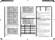
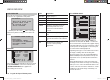
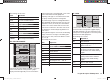
RX CURVE (EXPO)
RX CURVE
TYPE : B
CURVE1 CH : 02
TYPE : B
CURVE2 CH : 03
TYPE : B
CURVE3 CH : 04
Value Explanation Possible settings
CURVE1, 2
or 3 CH
Channel assign-
ment of the selec-
ted curve setting
1 … according to
receiver
TYPE Curve type A, B, C
see illustration
Servo travel
Transmitter control travel
Expo = +100%
–100%
+100%
0
–100%
+100%
0
Servo travel
Transmitter control travel
Expo = –100%
TYPE A
–100%
+100%
0
–100%
+100%
0
Servo travel
Transmitter control travel
linear
–100%
+100%
0
–100%
+100%
0
TYPE B
TYPE C
DR = 125% DR = 70%
In most cases a non-linear control function is used for
aileron (channel 2), elevator (channel 3) and rudder
(channel 4), and the default settings assume that this is
the case. BUT CAUTION: this assignment only applies if
you have not set either “2 ELE Sv” in the “Tail” line of the
“Basic settings” menu, or “2AIL” or “2AIL 2FL” in the “Ail
/ fl ap” line, at the transmitter. Otherwise control function
3 (elevator) is already split over control channels 3 +
6, and control function 2 (aileron) is split over control
channels 2 + 5 for the left and right ailerons. In both
these cases the corresponding receiver control channels
(INPUT CH) would then be channels 03 + 06 or 02 + 05.
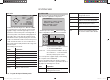
For example, if you have set “2AIL” at the transmitter,
and wish to use the RX CURVE option discussed here
instead of the “D/R Expo” menu (see page 82) of the
mx-12 HoTT transmitter - which offers more individual
adjustment options - then two curves must be set:
RX CURVE
TYPE : A
CURVE1 CH : 02
TYPE : A
CURVE2 CH : 05
TYPE : B
CURVE3 CH : 04
If you ignored this, the left and right ailerons would
exhibit different control characteristics.
The RX CURVE function can be used to manage the
control characteristics for up to three servos:
CURVE 1, 2 or 3 CH•
Select the desired control channel (INPUT CH) for
the fi rst servo.
The following setting in TYPE only affects the chan-
nel you select at this point.
TYPE
Select the servo curve:
A: EXPO = -100% and DUAL RATE = 125%
The servo responds slowly to stick movements
around the neutral position, but the curve becomes
steeper with increasing control travel.
B: Linear setting
33112_mx12_HoTT_2_GB.indd Abs45:12433112_mx12_HoTT_2_GB.indd Abs45:124 06.06.2011 19:39:4306.06.2011 19:39:43