
User's Manual

126
Program description: Telemetry menu
ALARM VOLT (low receiver voltage warning)
ALARM VOLT monitors the receiver voltage. The thresh-
old can be set to any value within the range 3.0 to 6.0
Volt. If the voltage falls below the set alarm limit, an
audible signal (interval beeping, long / short) is trig-
gered, and “VOLT.E” fl ashes at top right in all “RX …”
screen displa
ys:
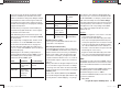
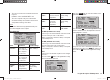
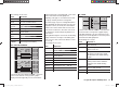
RX SERVO
REVERSE : OFF
CENTER : 1500μsec
TRIM : –000μsec
TRAVEL– : 150%
OUTPUT CH: 01
TRAVEL+ : 150%
PERIOD : 20msec
VOLT.E
The parameter “R-VOLT“ is also highlighted in the “RX
DATAVIEW” display:
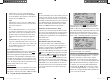
S–STR100% R–TEM.+28°C
L PACK TIME 00010msec
L.R-VOLT:03.5V
S–QUA100%S–dBM–030dBM
SENSOR1 :00.0V 00°C
SENSOR2 :00.0V 00°C
R-VOLT :03.7V
RX DATAVIEW VOLT.E
ALARM TEMP +/- (receiver temperature monitor)
These two options monitor the temperature of the
receiver: a lower limit value “ALARM TEMP-” (-20 ...
+10°C) and an upper limit value “ALARM TEMP+” (50 ...
80°C) can be programmed. If the temperature exceeds
the upper limit or falls below the lower one, an audible
signal (continuous beeping) is triggered, and “TEMP.E”
appears at top r
ight in all receiver displays. The param-
eter “R-TEM“ is also highlighted in the “RX DATAVIEW”
display.
Ensure that the receiver remains within the permitted
temperature range under all fl ight conditions (ideally
between -10 and +50°C).
CH OUTPUT TYPE
At this point you can select how the receiver outputs are
to be addressed.
ONCE•
The receiver servo sockets are addressed in se-
quence; this is recommended for use with analogue
servos. At this setting the servos are automatical-
ly operated at a frame rate of 20 ms (30 ms with the
twelve-channel receiver, Order No. 33512) - regard-
less of what is set or displayed in the “PERIOD” line
of the “RX SERVO” display.
SAME•
The receiver servo sockets are addressed in parallel
blocks of four, i. e. if you are using the GR-12 receiv-
er included in the set, channels 1 to 4 and channels
5 and 6 each receive their control signals simultane-
ously.
This is recommended for use with digital servos, and
especially where multiple servos are employed for
a single function (e. g. ailerons), to ensure that the
groups of servos run absolutely synchronously.
If you are using digital servos, we recommend that
you set 10 ms in the “PERIOD” line of the “RX SER-
VO” display so that you can exploit the fast response
of these servos. If you are using analogue servos, it
is essential to select “20 ms”.
If you choose the faster setting, please take par-
ticular care when selecting the receiver power
supply: since up to four servos can start moving si-
multaneously, the load on the battery is fairly severe,
so it must be a high-performance type.
SUMO (Sum signal OUT)•
A HoTT receiver confi gured as SUMO constant-
ly generates what is known as a sum signal from the
control signals of all its control channels. This signal
is present, for example, at servo socket 8 of the GR-
16 and GR-24 receiver.
The receiver outputs are addressed in sequence at a
frame rate of 20 ms (30 ms with the GR-24 receiver,
Order No. 33512), even if you have set 10 ms in the
“PERIOD” line of the “RX SERVO” screen page.
Although primarily intended for “satellite mode” with
two HoTT receivers, as described below, the sum
signal generated by the receiver defi ned as SUMO
can also be used, for example, to control a fl ybar-
less system, or to control a fl ight simulator (using the
adapter lead, Order No. 33310).
In …
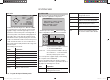
Satellite mode
… two HoTT receivers are inter-connected using a
three-core connecting lead (Order No. 33700.1 (300
mm) or 33700.2 (100 mm) by the highest-numbered
servo sockets. For more details on this please visit
www.graupner.de on the Internet.
All channels of the HoTT receiver which is confi gured
as SUMO, and is defi ned as the satellite receiver, are
constantly transferred to the second HoTT receiver -
the primary receiver - via this connection . The prima-
ry receiver must be programmed as the …
SUMI (Sum signal IN). •
Note that the signal only ever moves in one direction:
towards the SUMI.
However, if reception fails, the receiver defi ned as
SUMI only uses the sum signal coming from the
33112_mx12_HoTT_2_GB.indd Abs45:12633112_mx12_HoTT_2_GB.indd Abs45:126 06.06.2011 19:39:4306.06.2011 19:39:43