
User's Manual

135
Program description: Trainer system
The mx-12 HoTT Teacher transmitter can be linked to
any suitable Pupil transmitter - even those operating on
the “classic” 35 / 40 MHz band. For example, an mx-
12 HoTT Teacher transmitter can certainly be used in
conjunction with an mx-12s Pupil transmitter.
However, if the connection at the pupil end is NOT
made using a two-pole DSC socket, but instead - for
example - using a three-pin Trainer socket from the
Graupner range, the basic requirement for a correct
connection with a Pupil transmitter is that PPM (18
or 24) modulation must ALWAYS be set on the Pupil
transmitter, regardless of the modulation used by
the Teacher transmitter.
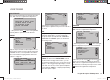
Pupil transmitter settings
The model to be controlled by the pupil must be pro-
grammed completely in a model memory of the Teacher
transmitter, i. e. with all its functions including trims and
any mixer functions, and the HoTT receiver in the model
must be “bound” to the Teacher transmitter. In principle,
however, an mx-12 HoTT Pupil transmitter can also be
linked to a Teacher transmitter operating on the “classic”
35 / 40 MHz band, since the PPM signal required from
the Teacher transmitter is present at the transmitter’s
DSC socket.
The Pupil transmitter can be virtually any transmitter
from the former and current Graupner range with at
least four control functions. More information on this is
available in the main FS catalogue, and on the Internet
under www.graupner.de.
Some transmitters will need to be retro-fi tted with the
appropriate module in order to act as the Pupil transmit-
ter.
This should be connected to the transmitter circuit board
as described in the installation instructions supplied in
the set. Information on the Pupil module required can
be found in the main Graupner FS catalogue and on the
Internet at www.graupner.de.
The Pupil transmitter must be connected to the Teacher
transmitter using the appropriate lead - see next double
page. The control functions of the Pupil transmitter
MUST act directly on the control channels, i. e. the
receiver outputs, without the intervention of any
mixers.
If you are using an “mc” or “mx” series transmitter,
it is best to set up a free model memory in the Pupil
transmitter with the required model type (“Fixed-wing”
or “Helicopter”). Assign the model name “Pupil” to the
memory, and set up the stick mode (Mode 1 … 4) and
“Throttle min. forward / back” to suit the pupil’s prefer-
ence. All the other settings should be left at the appropri-
ate default values. If you select the “Helicopter” model
type, the throttle / collective pitch direction and idle trim
must also be set accordingly on the Pupil transmitter. All
other functions, including mixer and coupling functions,
are carried out by the Teacher transmitter, which trans-
mits them to the receiver in the model.
If you are using a “D” or “FM” type transmitter, you
should check the servo directions and stick mode, and
alter them by re-connecting the appropriate leads if re-
quired. All mixers should be switched off or set to “zero”.
When assigning the control functions the usual conven-
tions should be observed:
Channel Function
1 Throttle / Collective pitch
2 Aileron / Roll
3 Elevator / Pitch-axis
4 Rudder / Tail rotor
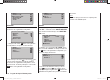
If you wish to transfer other control functions to the
Pupil transmitter, in addition to the functions of the two
dual-axis sticks (1 … 4), then you will need to assign
additional transmitter controls in the Pupil transmitter’s
“Transmitter control settings” menu to those inputs
which correspond to transmitter control numbers 5 and
/ or 6, as released in the Teacher transmitter’s “Trainer”
menu.
Important:
If you forget to assign a transmitter control, then •
the servo or servos concerned will remain in the
centre position when control is transferred to the
Pupil transmitter.
The Pupil transmitter must always be operated in •
PPM mode, regardless of the type of RF link be-
tween the Teacher transmitter and the model.
If the Pupil transmitter is connected using a DSC •
socket, then you should ALWAYS leave the Pu-
pil transmitter’s On / Off switch at the “OFF” posi-
tion, as this is the only way to ensure that the Pu-
pil transmitter module does not generate an RF
signal even when the DSC lead is plugged in.
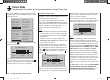
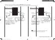
Trainer mode operations
Connect the two transmitters using the appropriate
lead; see the overview on the next page: connect the
plug marked “M” (Master) to the socket on the Teacher
transmitter, and the plug marked “S” (Student) (not
present on all leads) to the appropriate socket on the
Pupil transmitter.
33112_mx12_HoTT_2_GB.indd Abs41:13533112_mx12_HoTT_2_GB.indd Abs41:135 06.06.2011 19:39:4406.06.2011 19:39:44