
User's Manual


144
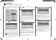
Programming example - fi xed-wing model
mx-12 HoTT programming techniques
Preparation, using a fi xed-wing model aircraft as an example
Programming model data into an mx-12 HoTT …
… is easier than it might appear at fi rst sight.
There is one basic rule which applies equally to all pro-
grammable radio control transmitters, and not just to the
mx-12 HoTT: if the programming is to go “smoothly”
and the systems work as expected, the receiving sys-
tem components must fi rst be installed correctly in the
model, i. e. the mechanical systems must be fi rst-rate.
This means: ensure that each servo is at its correct
neutral position when you fi t the output lever or disc
and connect the linkage to it. If you fi nd this is not the
case, correct it! Remove the output arm, rotate it by one
or more splines and secure it again. If you use a servo
tester, e. g. the RC-Tester, Order No. 2894.12, to centre
the servos, you will fi nd it very easy to fi nd the “correct”
position.
Virtually all modern transmitters offer facilities for offset-
ting the neutral position of servos, but this is no substi-
tute for a correct mechanical installation; this function is
only intended for fi ne tuning. Any substantial deviation
from the “0” position may result in additional asymmetry
when the signal undergoes further processing in the
transmitter. Think of it this way: if the chassis of a car
is distorted, you may be able to force the vehicle to run
straight by holding the steering wheel away from centre,
but it does not make the chassis any less bent, and the
basic problem remains.
Another important point is to set up the correct control
travels wherever possible by using the appropriate link-
age points in the mechanical system; this is much more
effi cient than making major changes to the travel set-
tings at the transmitter. The same rule applies: electronic
travel adjustment facilities are designed primarily to
compensate for minor manufacturing tolerances in the
servos and for fi ne adjustment, and not to compensate
for poor-quality construction and defective installation
methods.
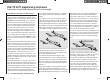
If two separate aileron servos are installed in a fi xed-
wing model aircraft, the ailerons can also be employed
as fl aps by defl ecting both of them down, and as air-
brakes by defl ecting both of them up - simply by setting
up a suitable mixer (see the section starting on the next
double page). Such systems are generally more often
used in gliders and electric gliders than in power models.
In such cases the servo output arms should be offset
forward by one spline relative to the neutral point, i. e.
towards the leading edge of the wing, and fi tted on the
servo output shaft in that position.
The mechanical differential achieved by this asym-
metrical installation takes into account the fact that the
braking effect of the up-going ailerons increases with
their angle of defl ection, and this means that much less
travel is usually required in the down-direction than the
up-direction.
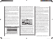
Similar reasoning applies to the installation of the fl ap
linkage when separately actuated fl ap servos are in-
stalled, designed to be used in a butterfl y (crow) system.
Here again an asymmetrical linkage point is useful. The
braking effect of the crow system is provided primarily
by the down-movement of the fl aps rather than the
up-movement of the ailerons, so in this case the servo
output arms should be angled aft, i. e. offset towards the
trailing edge of the wing, as this makes greater travel
available for the down-movement. When this combina-
tion of lowered fl aps and raised ailerons is used, the
ailerons should only be raised by a moderate extent, as
their primary purpose in this confi guration is to stabilise
and control the model rather than act as brakes.
You can “see” the difference in terms of braking effect by
deploying the crow system, then looking over and under
the wing from the front: the larger the projected area of
the defl ected control surfaces, the greater the braking
effect.
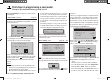
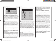
Outboard ailerons
Inboard camber-changing flaps
(This type of asymmetrical installation of the servo
output arms can also make sense when you are setting
up split fl aps or landing fl aps on a power model.)
Once you have completed your model and set up the
mechanical systems accurately in this way, you are
ready to start programming the transmitter. The instruc-
tions in this section are intended to refl ect standard
practice by describing the basic general settings fi rst,
and then refi ning and specialising them to complete the
set-up. After the initial test-fl ight, and in the course of
continued test-fl ying, you may need to adjust one or oth-
33112_mx12_HoTT_2_GB.indd Abs42:14433112_mx12_HoTT_2_GB.indd Abs42:144 06.06.2011 19:39:4606.06.2011 19:39:46