
User's Manual

149
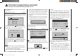
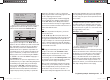
Programming example - fi xed-wing model
stick mode
motor at C1
1
no
tail type normal
aile/flap
mod name
2aile
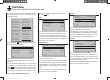
… and if you wish to be able to defl ect both ailerons up
using the throttle / br
ake stick (Ch 1), then a suitable
value should be entered in the “Brake ¼ AIL” line.
0%
0%
0%
0%
–––
–––
–––
–––
–––0%
ail
diff aile.
rudd
brak
brak
elev
aile
elev aile
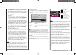
In principle the same applies to the “Brake ¼ FL”
line,
which also becomes available if you have selected “2AIL
2FL”, although the set value should cause the fl aps to
defl ect as far as possible in the downward direction
when the brake stick is operated. It is important to en-
sure that the servos do not strike their mechanical end-
stops. To achieve this, you may need to limit the servo
travel(s) for the servos concerned using the “TRAVEL-”
or “TRAVEL+” line on the “RX SERVO” display page of
the “Telemetry” menu.
If the ailerons are set up to act as simple brakes, as de-
scribed previously, or as part of the braking arrangement
in a butterfl y (crow) system, then you should always
enter a value for “Diff.-Red.” (“differential reduction” -
see page 93) - selecting 100% is the safe option here!
Differential reduction means that aileron differential is
suppressed proportionally only when you operate the
airbrake stick. The purpose of this is to increase the
down-going aileron travel on the landing approach, with
the aim of improving aileron response.
If the wing is equipped with two camber-changing fl ap
servos in addition to two separately actuated ailerons,
then the “AIL ¼ FL” (aileron ¼ fl ap) mixer transfers
the aileron movements to the fl aps; we suggest that the
fl aps should not follow the movement of the ailerons to a
greater extent than about 50%.
Note:
If you have only installed one fl ap servo, you should
leave this mixer at 0%.
The “FL ¼ AIL” (fl ap ¼ aileron) mixer works in the
opposite direction; depending on the layout of the model
we suggest values between about 50% and 100% for
this option. The fl aps are controlled using the transmitter
control or switch assigned to the input “E6”. Preferably,
however, one of the rotary proportional controls (CTRL 7
or 8) should be used for this.
Note:
We strongly recommend that you reduce the travel of
the fl aps to about 25% in the “Transmitter control
settings” menu, as this gives fi ner control of the fl ap
positions using the selected transmitter control.
The remaining options in the “Fixed-wing mixers” menu
are designed to provide further fi ne-tuning of multi-fl ap
wing systems, and are largely self-explanatory.
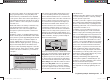
When you have completed the model-specifi c settings
up to this point, you are probably ready to consider the
model’s fi rst fl ight. At this juncture you should certainly
take the time to carry out a series of “dry runs”, i. e.
check all the settings thoroughly while the model is still
on the ground. Remember that a serious programming
error may damage more than just the model. If you are
not sure of any point, please ask an experienced model
pilot for advice.
If during the test phase you realise that one or other of
the settings needs to be changed in order to tailor the
model’s control response to your preferences - perhaps
the servo travels are too great or too small overall - then
we suggest that you turn to the …
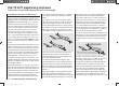
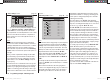
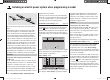
“D/R / Expo” menu (page 82)
122%
100%
111%
+11%
0%
aile
elev
rudd
DUAL EXPO
3
3
–––
+22%
normal
… in order to adjust the overall set-up to suit your
requirements and fl
ying style.
The Dual Rate function is used to adjust the relationship
between stick travel and control surface travel (see page
82). However, if it is only the model’s control response
around neutral which is too powerful for comfortable
fl ying, i. e. the maximum travels are acceptable, then
“Exponential” can be employed, either instead of Dual
Rates or in addition to them. If a physical switch is as-
signed to this function, you can switch between two Dual
Rate / Expo settings while the model is fl ying.
33112_mx12_HoTT_2_GB.indd Abs42:14933112_mx12_HoTT_2_GB.indd Abs42:149 06.06.2011 19:39:4606.06.2011 19:39:46