
User's Manual

150
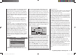
Programming example - fi xed-wing model
Including an electric power system when programming a model
An electric power system can be controlled in various
ways:
The simplest method of including such a power plant
in a model program is to use the throttle / brake stick
(Ch 1). However, in the preceding programming instruc-
tions we have already reserved the Ch 1 transmitter
control for the airbrakes, which means that we have to
explore other possibilities for controlling the motor: one
is to use the switchable solution described in the section
starting on page 152, and another is to use an alterna-
tive transmitter control. A suitable option is one of the
two three-position switches SW 4/5 or 6/7, and another
is one of the rotary proportional controls CTRL 7 or 8.
However, another alternative would be the two-position
switch SW 3. The deciding factor in your choice ought to
be that the switch is within easy reach of your fi ngers.
Example 1
Using one of the rotary proportional knobs
CTRL 7 or 8
If one of these transmitter controls is used, the set-up is
extremely easy. All you have to do is connect the speed
controller to a vacant receiver servo socket 5 or 6.
However, please bear in mind that outputs 2 + 5 and 6
+ 1 may already be linked together, depending on the
model type you have selected and the number of aileron
and fl ap servos in your model.
Connect your speed controller to the next vacant input,
and assign one of the rotary proportional controls CTRL
7 or 8 - in our example CTRL 7 - to the selected input -
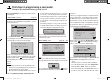
for example, “I6”. This is accomplished in the …
“Transmitter control settings” menu (page 74)
Use the arrow buttons cd of the left or right-hand
four-way button to select the desired line. Pressing the
central SET button of the right-hand four-way button
activ
ates “Switch / transmitter control assignment”. Now
turn the knob of the rotary proportional control: after a
brief delay the entry “ctrl 7” will appear in the highlighted
fi eld:
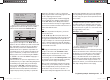
I5
I6
+
trv
ctrl 7
+100%
+100%
+100%
+100%
free
In the third column you can adjust servo travel to suit the
speed controller y
ou are using; alternatively you could
use the “-Travel+” column in the …
“Servo settings” menu (page 72).
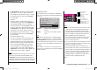
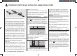
S2
S3
S4
rev cent
+
trav
0%
0%
0%
100%
100%
100%
100%
100%
100%
0%
0%
100%
100%
100%
100%
S5
S6
The last stage is to check the settings, so move from the
basic display to “Servo display”, typically by simultane-
ously pressing the ef buttons of the left-hand four-
way button: In the “OFF” position of the rotary control
CTRL 7 the control channel you have selected - in this
example channel “6” - should be at -100%, and at the
“full-throttle” setting at +100%.
Example 2
Using a two-position switch, SW 3
This variant implements a pure ON / OFF function, and
results in the motor starting “abruptly” … unless the
speed controller you are using features what is known
as a “soft start” function.
At the receiving end you need either a simple electronic
switch or - if you want a smoother motor start - a suit-
able speed controller.
The settings for this arrangement are entered in the …
“Transmitter control settings” menu (page 74)
First check which receiver socket (5 or 6) is available
for connection to your speed controller. If you have
assigned two aileron servos in the “Basic settings”
menu, and if you have not connected any other auxiliary
function, then this would be channel 6; this is the option
we will use in our example.
First set the selected switch to the “OFF” position, then
use the arrow buttons cd of the left or right-hand four-
way button to select the desired line in the menu. Press
the central SET button of the right-hand four-way button
to activ
ate “Switch / transmitter control assignment”,
then move the selected switch from the “OFF” position
to the “ON” position. The highlighted fi eld now shows the
switch number together with a symbol which indicates
the direction of switching:
33112_mx12_HoTT_2_GB.indd Abs42:15033112_mx12_HoTT_2_GB.indd Abs42:150 06.06.2011 19:39:4606.06.2011 19:39:46