
User's Manual

156
Programming example - fi xed-wing model
Using fl ight phases
Within any of the ten model memories you can program
up to three different fl ight phases (states of fl ight), each
incorporating settings which can be entirely different
from the others.
Each fl ight phase can be called up by means of a switch.
Flight phases represent the simplest and most conven-
ient method of switching between different model set-
tings in fl ight, and are programmed for different stages
of a typical fl ight, such as “normal”, “thermal”, “speed”,
“distance” etc.
We assume that you have already programmed the
model in the transmitter’s model memory, set it up care-
fully, test-fl own it and trimmed it out properly. First move
to the …
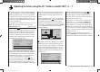
“Basic settings” menu (pages 56 … 62)
aile/flap 2ail2fl
timer
5:00
3
phase 2
phase 3
takeoff
speed
–––
–––
tail type normal
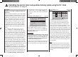
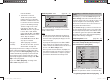
… and then to the line “Phase 2” and / or “Phase 3”,
where y
ou can either accept the default name or assign
a specifi c, more appropriate, name to each fl ight phase.
The purpose of this name is just to help you differentiate
between the fl ight phases; it has no signifi cance in terms
of programming. It will later appear in the transmitter’s
basic screen display, and also in the “Phase trim” and
“D/R Expo” menu.
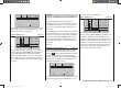
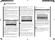
A physical switch must be assigned so that you can
select the different fl ight phases. The ideal one for
switching a maximum of three fl ight phases is one of the
three-position switches SW 4/5 or 6/7, located at front
left and right on the transmitter.
Each of the two end-points of this switch should be
assigned to one fl ight phase, starting from the centre
position. We recommend that the switch direction should
match the phase numbering: as shown in the left-hand
illustration, for example, “Phase 2” is “forward” from the
centre position, while “Phase 3” is “back” (towards you).
Select the appropriate line, name, and switch assign-
ment in the “usual” way, i. e. using the various four-way
buttons.
5:00
3
4
5
aile/flap 2ail2fl
timer
phase 2
phase 3
takeoff
speed
tail type normal
Note:
In principle it makes no difference which names you as-
sign to the various phases - with the exception of Phase
1, which is assigned the name “normal”, and is always
active when fl ight phases 2 and 3 are disabled.
For general model fl ying three fl ight phases are usually
quite suffi cient:
“Launch” or “Thermal” for launch and “staying up”,•
“Normal” for normal conditions, and•
“Speed” for fl ying in “top gear”.•
At this point all three phases have been set up and
assigned names, and you can switch between them;
however … if you operate the phase switch you will soon
notice that nothing has changed, i. e. all the settings for
the control surfaces, and especially the wing fl aps, are
the same.
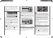
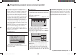
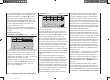
To change these settings, call up the …
“Phase trim” menu (page 86)
… move the phase switch (or switches) to the appropri-
ate position, and enter the desired values in the stand-
ard way by pressing the input buttons, in a similar way to
the method of adjusting transmitter control centres and
offsets with other radio control systems.
normal 0%
0%
0%
¿
+2%
4%
+8%
–3%
–5%
–7%
P H A S E T R I M
takeoff
speed
AIL ELEFLA
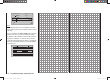
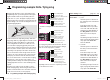
If you now switch the receiving system on and select the
diff
erent phases in turn, you will see a difference in con-
trol surface response. The differences are also refl ected
in the bar display for the servos in the “Servo display”
menu, which you can call up from virtually any menu
position by simultaneously pressing the ef buttons of
the left-hand four-way button.
Note:
Depending on the information you have entered in the
“aile/fl ap” line of the “Basic settings” menu, the “ELE”
column alone, the “AIL” and “ELE” columns, or - as
shown above - “FLAP”, “AIL” and “ELE” may appear on
the screen for “Phase trimming”.
33112_mx12_HoTT_2_GB.indd Abs42:15633112_mx12_HoTT_2_GB.indd Abs42:156 06.06.2011 19:39:4706.06.2011 19:39:47