
User's Manual

157
Programming example - fi xed-wing model
Programming example: servos running in parallel
In some cases a second servo is required to run in
parallel with an existing servo; for example, if a second
elevator or rudder is to be actuated by a separate servo,
or where a second servo is needed to cope with very
high control forces, or where two servos are required for
a large control surface due to the high forces involved.
This task could be solved simply by connecting both ser-
vos together in the model using a conventional Y-lead.
However, this has the drawback that the linked servos
cannot be adjusted individually from the transmitter, i. e.
you forfeit the basic advantage of the computer radio
control system: separate adjustment of individual servos
from the transmitter.
Another option would be to call up the Telemetry menu
and use its “Channel mapping” option instead of a
simple Y-lead; see page 121. However, the simplest
method is to use the transmitter’s software facilities. For
example, it is easy to set up …
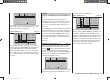
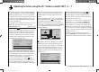
Two elevator servos
… to operate in parallel. First move to the …
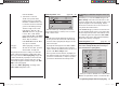
“Basic settings” menu (page 56 … 62)
mod name
stick mode
motor at C1
1
idle re.
tail type
GRAUBELE
cut off +150%–100%
–––
2elev sv
… and set “2elev sv” in the “tail type” line.
The tw
o elevator servos are then connected to receiver
output sockets 3 and 6.
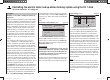
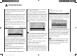
Two rudder servos
In this example we will connect two rudders “in parallel”
using the “Free mixers” menu. The second rudder could
be connected to receiver output 6, which is not already
in use.
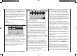
The fi rst step is to move to the …
“Free mixers” menu (pages 107 … 111)
typ fro
to
M1
M2
M3
??
??
rd
??
6
??
tr
… and set up a mixer “Tr RUD ¼ 6”.
In the “Type” column select the “Tr” setting, so that the
rudder trim affects both rudder servos.
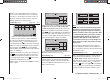
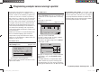
Finally switch to the graphics page and set a SYMmetri-
cal mixer input of +100%:
MIX1 rd 6
trv
0%Offs
ASYSYM
+100%
+100%
tr
Once again, for safety reasons it is really essential that
y
ou set input 6 to “free” in the “Transmitter control
settings” menu.
As an added refi nement, you may want both rudders
to defl ect outwards only, as part of a braking system
controlled by the Ch 1 stick. This can be accomplished
by setting up two additional mixers “c1 ¼ 4” and “c1 ¼
second rudder control channel” - in our case “6” - with
suitable servo travel settings. An offset of +100% is then
selected for both mixers, as the Ch 1 stick is (usually) at
its top end-point when the airbrakes are retracted, and
the winglet rudders are only required to defl ect outwards
proportionally when the brakes are extended.
33112_mx12_HoTT_2_GB.indd Abs42:15733112_mx12_HoTT_2_GB.indd Abs42:157 06.06.2011 19:39:4706.06.2011 19:39:47