
User's Manual

158
Programming example: delta and fl ying wing
On page 144, where the section on fi xed-wing model
prog
ramming starts, you will fi nd general notes regard-
ing the installation and set-up of the RC system in a
model, and - of course - this applies equally to deltas
and fl ying wings. The information on test-fl ying and refi n-
ing the settings is also relevant, including the section on
programming fl ight phases.
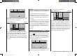
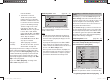
left
right
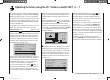
In their characteristic shape and geometry, deltas and
fl ying wings differ very signifi cantly from “normal” models
even at fi rst sight, but the differences in the requisite
servo arrangement are rather more subtle. The “clas-
sic” model delta or fl ying wing generally has only two
control surfaces, which act both as ailerons (in opposite
directions) and as elevators (in the same direction), in a
similar way to the superimposed rudder / elevator func-
tions of a V-tail. More modern designs tend to be more
complex; one (or two) inboard control surfaces may be
used purely as elevators, while the outboard ailerons
also act as elevators, but to a reduced extent. If a fl ying
wing has four or even six wing control surfaces, it is
certainly feasible nowadays to set them up with camber-
changing fl ap functions and / or even a butterfl y (crow)
system.
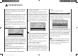
However, most of these models still rank as “classic”
deltas and fl ying wings, with two wing-mounted control
surfaces, and for them the servos should be connected
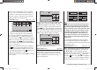
to the receiver as follows (see also page 43):
Free or telemetry sensor or auxiliary function
Receiver power supply
Receiver power supply
Airbrakes or throttle or speed
controller (electric motor)
Free or rudder
Left elevon (aileron / elevator) servo
Right elevon (aileron / elevator) servo
Free or auxiliary function
… and with four wing-mounted control surfaces as fol-
lows:
Right flap (aileron) / elevator
Receiver power supply
Receiver power supply
Airbrakes or throttle or speed
controller (electric motor)
Free or rudder
Left elevon (aileron / elevator) servo
Right elevon (aileron / elevator) servo
Left flap (aileron) / elevator
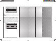
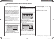
If your fl ying wing features inboard elevators, the “nor-
mal” servo sequence has proved useful; this arrange-
ment can also be employed for “canards”:
Right elevon (aileron / elevator)
Receiver power supply
Receiver power supply
Airbrakes or throttle or speed
controller (electric motor) or
alternatively right flap (/ elevator)
Rudder (if present)
Left elevon (aileron / elevator) servo
Elevator (if present)
Left flap (/ elevator)
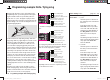
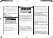
Depending on the receiver servo sequence you select,
you should fi rst move to the …
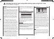
Programming example: Delta / fl ying wing
“Basic settings” menu (pages 56 … 62)
… and select the following options in each line:
“motor at C1”: • “none”:
The brake system is “retracted” at
the “forward” position of the throttle /
brake stick.
In the “Aileron / fl ap” line of the
“base sett.” menu it is possible to
select “1AL”, “2AL” and “2AL 2FL”,
and the mixers “Brake ¼ NN*” in
the “Wing mixers” menu and all
mixers “from” and “to” fl aps are
activated.
The warning message “Throttle too
high” (see page 28) and the “Motor
stop” option in the “base sett.”
menu are disabled.
• “none/inv”:
The brake system is “retracted” at
the “back” position of the throttle /
brake stick.
In the “Aileron / fl ap” line of the
“base sett.” menu it is possible to
select “1AL”, “2AL” and “2AL 2FL”,
and the mixers “Brake ¼ NN*” in
the “Wing mixers” menu and all
mixers “from” and “to” fl aps are
activated.
The warning message “Throttle too
high” (see page 28) and the “Motor
stop” option in the “base sett.”
* NN = Nomen Nominandum (name to be stated)
33112_mx12_HoTT_2_GB.indd Abs47:15833112_mx12_HoTT_2_GB.indd Abs47:158 06.06.2011 19:39:4706.06.2011 19:39:47