
User's Manual

160
Programming example: delta and fl ying wing
“normal” four-fl ap wing (two ailerons and two fl aps), and
therefore has all the options associated with this wing
type. The method involves the “elev ¼ NN *” mixers,
which were originally intended only for pitch trim com-
pensation and non-standard applications. In this case
they are “abused” by setting higher values than normal,
in order to transfer the elevator signal to the control
surfaces of the tailless model.
However, none of the fi xed-wing mixers includes the
digital trim of the elevator stick - so an alternative has to
be found.
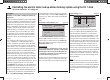
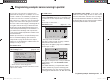
Start by switching to the …
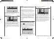
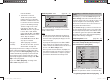
“Transmitter control settings” menu (page 74)
I5
I6
+
trv
+15%
+15%
ctrl 6
ctrl 6
+15%
+15%
… and assign the same tr
ansmitter control to the inputs
5 and (if required) 6, e. g. the rotary proportional control
CTRL 7. Now move to the “Travel” column and reduce
the travel of the transmitter control for these two inputs
symmetrically to around 50%, or even less, because: the
lower this value, the fi ner the trim control.
However, if you prefer to use the normal elevator trim
lever, set - or leave - the “elev ¼ NN *” mixers to 0%,
and instead set up free linear mixers to do the job.
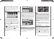
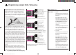
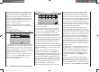
This is done by calling up the …
“Free mixers” menu (pages 107 … 111)
typ fro
to
M1
M2
M3
el
6
el
??
5
??
tr
tr
… and setting up one linear mixer “Tr elev ¼ 5”, and - if
necessary - “Tr elev ¼ 6”.
Move to the graphic page of this menu to set the re-
quired mixer ratios. Check the settings, and above all
the direction of effect, in the “Servo display”, or on the
model itself, and change the prefi xes if necessary.
If you carry out the programming as described above,
the ailerons will also move in the same direction, like
fl aps, when you move the elevator stick. The effect of the
“tr” option is that the elevator trim lever also affects the
associated mixer when you operate the elevator stick.
Since an additional transmitter control is no longer
required for this arrangement, you should disable input 5
and (if used) input 6 in the second column of the “Trans-
mitter control settings” menu; simply set these inputs
to “free”.
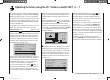
Many years ago, the author fl ew a model delta pro-
grammed exactly in this way using the mc-20, with
the following additional refi nements: “fl ap settings” used
as trim, and butterfl y (crow) as landing aid - the latter
exploiting the “Brake ¼ AIL” and “Brake ¼ FL” wing
mixers to provide complete compensation for pitch trim
changes in both directions. In this case the term “ailer-
ons” means the outboard wing control surfaces, and
“fl aps” the inboard pair of control surfaces.
A modern sweptback fl ying wing can be controlled in
a similar fashion. These models also feature inboard
and outboard control surfaces: the former forward of
the Centre of Gravity, the latter aft of it. Defl ecting the
inboard control surface(s) down increases lift and pro-
duces an up-elevator effect; defl ecting them up creates
the opposite effect. In contrast, the outboard ailerons act
in the reverse direction: a down-defl ection produces a
down-elevator effect, and vice versa. There are really no
limits to what can be achieved with appropriate settings
of the system’s sophisticated mixers.
However, please note that you should be extremely
careful when setting differential travel with such a con-
fi guration, regardless of your model’s set-up, its tail type
and the number of servos you are using. This is because
differential travels on a tailless model tend to produce
an asymmetrical elevator effect, rather than the desired
adverse yaw reduction. For this reason it is advisable
to start with a differential setting of 0% - at least for the
fi rst few fl ights. When you are familiar with the model
and feel the need to experiment, it may then be feasible
under certain circumstances to try differential settings
deviating from zero.
For larger models it could be advisable to install winglets
fi tted with rudders, i. e. small vertical surfaces at the
wingtips. If these are actuated by two separate servos,
they can be controlled as described in the example on
page 157 dealing with “Servos running in parallel”, or
using “Channel mapping” in the “Telemetry” menu; see
page 121.
You may also want both rudders to defl ect outwards
when a braking system is operated using the Ch 1 stick,
and this can be accomplished as follows: if you have
selected the “normal” tail type, set up two further mixers
“c1 ¼ 4” and “c1 ¼ second rudder control channel”
33112_mx12_HoTT_2_GB.indd Abs47:16033112_mx12_HoTT_2_GB.indd Abs47:160 06.06.2011 19:39:4706.06.2011 19:39:47