
User's Manual

164
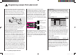
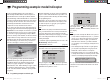
Programming example: F3A model
This completes the basic set-up for a typical F3A model.
Correcting model-specifi c errors
It is an unfortunate fact of life that even very carefully
built models exhibit minute faults and inaccuracies which
produce unwanted deviations when the model is fl ying;
the mixers of a computer radio control system are then
needed to compensate for these defi ciencies. In this
section we will describe how to carry out the adjust-
ments required, but please note the following points
before we get started: it is vital to ensure that the model
is built as accurately as humanly possible, is balanced
perfectly around the lateral and longitudinal axes, and
that motor downthrust and sidethrust are set correctly.
Rudder causes unwanted movement around the 1.
longitudinal and lateral axes
It is often the case that a rudder command caus-
es the model to rotate slightly around the longitudi-
nal and / or lateral axis. This is particularly trouble-
some in what is known as knife-edge fl ight, where the
model’s total lift is generated by the fuselage, aided
by the rudder defl ection. The result is that the mod-
el rotates and changes heading slightly, as if the pi-
lot were applying aileron or elevator at the same time.
These tendencies have to be corrected with compen-
sation around the lateral axis (elevator) and around
the longitudinal axis (aileron).
These corrections can be achieved easily with the
mx-12 HoTT, exploiting the “free mixers” once
again. For example, if the model rotates to the right
around the longitudinal (roll) axis when the rudder
is defl ected to the right for a knife-edge pass, then
a mixer is set up which defl ects the ailerons slight-
ly to the left. Heading changes around the lateral (el-
evator) axis can be corrected in a similar way using a
mixer acting upon the elevator:
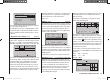
a) Correction around the lateral axis (elevator)
MIX “rd ¼ el”
ASYmmetrical setting. The exact values required
must be found by fl ight testing.
b) Correction around the longitudinal axis (aileron)
MIX “rd ¼ al”
ASYmmetrical setting. The exact values required
must be found by fl ight testing.
In most cases relatively small mixer values are called
for - typically below 10% - but this does vary from
model to model.
Vertical climb and descent2.
Many models exhibit a tendency to deviate from the
ideal line in vertical climbs and descents. To correct
this we need an elevator neutral position which varies
according to the throttle setting. For example, if the
model tends to pull out of a vertical descent by itself
when the motor is throttled back, slight down-elevator
must be mixed in at this throttle setting.
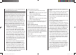
MIX “c1 ¼ el”
As a rule you will need to set mixer values below 5%,
but once again there is no substitute for test-fl ying.
Rolling (movement around the longitudinal axis) 3.
at idle
When you reduce the throttle setting, the model may
tend to roll slightly in one direction. Clearly an ai-
leron correction must be made. However, it is much
more elegant to let a mixer correct this effect for you
than to move the stick manually. Once again, a mixer
needs to be set up:
MIX “c1 ¼ al”
As a rule you will need to set mixer values below 5%,
but once again test-fl ying is called for.
The adjustment process should only be carried out
in calm weather. Often all you need to do is apply the
mixer in the control segment between half-throttle
and idle. To achieve this, leave the Offset point at the
centre position, and set up the mixer ASYmetrically.
Rolling when ailerons and fl aps are extended4.
If you fl y the landing approach with both ailerons de-
fl ected up, the model may show a tendency to roll
slightly due to minor variations in aileron servo trav-
el (or constructional inaccuracies); i. e. the model may
turn to either side by itself. Once again, this tenden-
cy can easily be corrected using a mixer to vary the
compensation according to the position of the ailer-
ons / landing fl aps.
MIX ”c1 ¼ al”
It is essential to provide a means of switching the
mixer on and off using the switch which controls the
aileron / landing fl ap function (see previous page), to
ensure that this mixer only has any effect when the
aileron / landing fl ap function is activated. The opti-
mum value has to be found by test-fl ying.
And fi nally a few words on the …
33112_mx12_HoTT_2_GB.indd Abs46:16433112_mx12_HoTT_2_GB.indd Abs46:164 06.06.2011 19:39:4706.06.2011 19:39:47