
User's Manual

168
Programming example: model helicopter
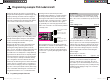
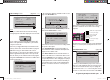
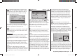
“Transmitter control settings” menu (page 76)
+
trv
free
ctrl7
thr
gyr
lim
+100%
+100%
+100%
+100%
+100%
+100%
free
… will show you that “ctrl 7”, i. e. the rotary proportional
control CTRL 7, is assigned to the
“Lim” input, whereas
all other inputs are programmed to “free” by default. The
“Lim” input serves as throttle limiter. It acts solely on
output “6”, to which the throttle servo is connected.
Just to remind you:
Using the “Throttle limiter” function eliminates the •
need to program an “Idle-up” fl ight phase.
The throttle limiter does not control the throttle ser-•
vo; it simply limits the travel of this servo in the for-
ward direction, according to the setting of the throt-
tle limiter, when required. The throttle servo is usually
controlled by the collective pitch stick via the throttle
curve or curves you have set in the “Helimix” menu,
for which reason input 6 should always be left “free”.
For more details please refer to the sections on pag-
es 96 and 97 of the manual.
Moreover the Ch 1 trim only affects a helicopter’s •
throttle servo. This section does not describe the spe-
cial features of this trim (“cut-off trim”) again, as it
is covered on page 40. (Thanks to the digital trims,
trim values are automatically stored when you switch
models and when you switch between fl ight phases.)
You will fi nd a detailed description of the basic idle •
set-up procedure and the method of adjusting idle
and throttle limit in the section starting on page 79.
settings” menu.
Note:
Please note one important difference in later Graupner
mc and mx radio control systems compared with
earlier equipment: the fi rst collective pitch servo and the
throttle servo have been interchanged.
Now move to the …
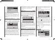
“Servo settings” menu (page 72),
S1
S2
S3
rev cent
+
trav
0%
0%
0%
100%
100%
100%
100%
100%
100%
0%
0%
100%
100%
100%
100%
S4
S5
… where you can set up the travels and directions of
rotation of the individual servos. The basic aim here
should be to keep servo travels at 100% wherever
possible, as this maintains best possible resolution and
accuracy. Use “Rev.” if necessary to change the direc-
tion of rotation of any servo; do check carefully that the
direction you set really is correct. The tail rotor servo,
in particular, must operate in such a way that the nose
(!) of the helicopter moves in the direction which corre-
sponds to the movement of the tail rotor stick.
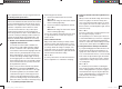
A glance at the …
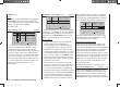
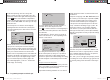
Now use the arrow button f of the left or right-hand
four-way button to move to the “Travel” column, and
increase the value in the highlighted fi eld from 100% to
125%, with the throttle limiter at its forward end-stop.
+
+100%
+100%
+100%
+100%
+100%
+125%
trv
free
ctrl7
thr
gyr
lim
free
This ensures that the throttle limiter cannot possibly
restr
ict the full throttle travel dictated by the collective
pitch stick when the model is in fl ight.
Set-up note for electric helicopters:
Since electric motors by their nature require no idle
setting, the only important point when setting up an
electric-powered model helicopter is that the adjustment
range of the throttle limiter should be set signifi cantly
higher and lower than the adjustment range of the
speed controller, which is usually from -100% to +100%.
It may therefore be necessary to adjust the “Travel” value
of the throttle limiter to an appropriate value, such as a
symmetrical 110% setting. However, further fi ne-tuning
can be carried out exactly as described here for the
glow-powered machine.
An additional function needs to be activated in the …
“Basic model settings” menu (pages 64 … 71).
Even if you are a beginner to fl ying and are not yet
ready for this, it is advisable at least to defi ne the auto-
rotation switch, so that you have an “emergency cut”
switch for the motor. This is carried out by selecting the
“Auto-rotation” line using the arrow buttons cd of the
33112_mx12_HoTT_2_GB.indd Abs48:16833112_mx12_HoTT_2_GB.indd Abs48:168 06.06.2011 19:39:4806.06.2011 19:39:48