
User's Manual

169
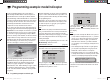
Programming example: model helicopter
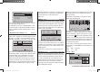
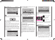
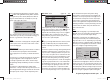
left or right-hand four-way button, pressing the central
SET button of the right-hand four-way button, and then
moving the two-position switch (SW 3) to the “ON” set-
ting. The switch number (in our example “3”) now ap-
pears on the right of the screen:
rear
5:00
C3
3
–––
phase 2 hover
pitch min
timer
autorotat.
rotor direct
right
This switch should be located at a position on the trans-
mitter where y
ou can easily reach it without letting go of
the stick, e. g. above the collective pitch stick.
Note:
For more information on setting up this “emergency OFF
switch” please refer to the section in the centre column
of the following page.
And another tip:
Please make it a habit to give all the switches a common
“on” direction; then a quick glance at the transmitter
before fl ying will soon reassure you that all switches are
“off”.
If you wish, you could at this point move up one line and
assign a fl ight phase switch for fl ight phase 2, which
is already assigned the name “Hover”, but this simple
programming example deliberately excludes such refi ne-
ments.
You have now completed the basic settings at the
transmitter, i. e. the procedure which you will need to use
time and again when setting up a new model. The actual
helicopter-specifi c set-up is carried out primarily in the …
“Heli mixers” menu (pages 94 … 105).
ch1
ch1
ptch
thro
tail
normal
gyro
0%
SEL
swash lim. off
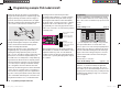
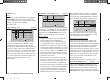
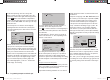
In the very fi rst line you will see the “Collective pitc
h”
function, and a brief press on the central SET button of
the right-hand four-way button takes you to the ap-
propriate sub-menu. At this point you will see a graphic
representation of the collective pitch curve. This is
initially defi ned by only three reference points, and in
most cases this is quite adequate.
Tip:
Always try to manage with these three reference points
initially, as additional points just complicate matters,
and extra complexity is just what you don’t need at the
moment.
The reference point for hovering should generally be the
mechanical centre-point of the collective pitch stick, as
this position feels completely natural to most pilots. You
can, of course, set up the curve to locate the hover at a
different point, but you should not be tempted to do this
unless you know exactly what you are doing. Start by
setting the collective pitch stick to centre. Assuming that
you previously adjusted the servos in accordance with
the manufacturer’s instructions, the servo output arms
will now (usually) be at right-angles to the servo case.
If you have not already done so, adjust the mechani-
cal linkages to the rotor head so that all the blades are
set to a collective pitch angle of 4° to 5° positive for the
hover. All known helicopters will fl y at this setting.
Now push the collective pitch stick fully forward to the
maximum collective pitch point (the full-length vertical
line indicates the current position of the stick). Adjust
Point 5 on the collective pitch curve using the arrow
buttons of the right-hand four-way button, with the aim of
obtaining a maximum collective pitch setting of around
9° at the main rotor blades. This point should be at a
value of around +50%.
Note:
A rotor blade set-up gauge, e. g. the Graupner item,
Order No. 61, is very useful when setting up blade pitch
angles, as you can read off the angles directly.
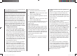
Now pull the collective pitch stick right back to the
collective pitch minimum position. Set the blade pitch
angle for Point 1 to 0 to -4°, depending on your piloting
ability. This produces a graph line with a slight angle at
the hover point, forming what is known as the collective
pitch curve. It might look approximately like this:
input
output
point
5
–100%
–80%
–80%
ptch
normal
If you now switch to the auto-rotation phase - you will
see the name of the fl
ight phase “Autorot” at bottom left
on the screen - the “old” collective pitch curve will re-ap-
pear. In this phase you should set the same values as in
the normal phase, with the following exception: increase
the pitch angle at Point 5 (collective pitch maximum) by
about 2°. This gives slightly more pitch for fl aring the
33112_mx12_HoTT_2_GB.indd Abs48:16933112_mx12_HoTT_2_GB.indd Abs48:169 06.06.2011 19:39:4806.06.2011 19:39:48