
User's Manual

170
Programming example: model helicopter
model when practising “autos” at a later (!) date.
Once you have set up the collective pitch curve, oper-
ate the auto-rotation switch again, then briefl y press the
central ESC button of the left-hand four-way button to
retur
n to the helicopter mixer menu select point. Now we
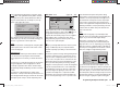
move on to the “Ch1 ¼ thro” line, where you can set up
the throttle curve.
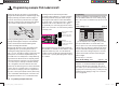
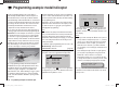
The fi rst step here is to enter the idle trim range by
adjusting the throttle curve. Move the collective pitch
stick to the minimum position, and set Point 1 to a value
of around -65%.
input
output
point
5
–100%
–65%
–65%
c1
normal
thro
With the throttle limiter closed and the idle tr
im fully
open, pull the collective pitch stick to the “fully back”
position and move it slightly to and fro: the throttle servo
should not respond to this movement. This arrangement
gives you a seamless transition from idle trim to the
throttle curve. You will probably need to make further ad-
justments to the throttle curve, but this process must be
carried out later as part of the fl ight-testing procedure.
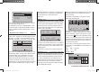
If you now switch temporarily from this graph to the
auto-rotation fl ight phase, you will see - instead of the
usual display - the following:
c1
Autorot
thro
off
This means that the throttle servo has switched to a
fi
xed value, which can be adjusted as follows:
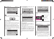
Press ESC to return to the menu list. Assuming that you
are still in the auto-rotation phase
, this will now include
new sub-menus.
The important line is “Throttle”, where you should set
a value of around +125% or -125%, depending on the
direction of servo rotation.
tail
ptch
thro
Autorot
gyro
0%
SEL
0%
–125%
swash lim. off
This setting ensures that the motor stops reliably in
the auto-rotation phase (to allow you to cope with an
emergency). Later, when you have gained suffi cient
experience to practise auto-rotation landings, the setting
should be changed to a value which provides a reliable
idle.
Set-up note for electric helicopters:
Since the motor must be stopped completely if an emer-
gency occurs with an electric-powered model helicopter,
this setting can be adopted unchanged.
At present the remaining sub-menus are of no interest.
Simply switch “Auto-rotation” off, and move back to the
fi rst menu list.
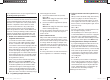
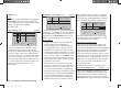
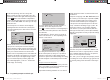
Call up the set-up page of the “Ch1 ¼ tail rotor” menu:
this is where you set static torque compensation (DMA)
for the tail rotor. Once again, please restrict yourself
to the three default reference points; everything else
is the preserve of the experienced pilot. For the initial
set-up - intended for a heading-lock gyro system - the
uniform pre-set values of 0% should be changed to
-30% at Point 1 (collective pitch minimum) and +30%
at the opposite end, Point 5 (collective pitch maximum),
although you may fi nd it necessary to adjust the settings
slightly later.
input
output
point
5
–100%
–30%
–30%
c1
normal
tail
Now switch back to the auto-rotation phase for a mo-
ment.
The set-up curve is disabled here, with the result
that the tail rotor servo no longer responds to collective
pitch commands (when the main rotor is not powered,
there is no rotor torque to be corrected).
The - static - pre-set of the gyro effect principle (“normal”
or “heading lock” mode), and also the gyro gain can now
be altered by setting a value other than “0” in the “Gyro”
line:
33112_mx12_HoTT_2_GB.indd Abs48:17033112_mx12_HoTT_2_GB.indd Abs48:170 06.06.2011 19:39:4806.06.2011 19:39:48