
User's Manual

171
Programming example: model helicopter
ch1
ch1
ptch
thro
tail
normal
gyro
0%
SEL
swash lim. off
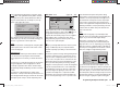
Please be sure to read and observe the set-up
instructions supplied with y
our gyro at this point,
as there is a possibility that your helicopter will be
uncontrollable if you set it up incorrectly!
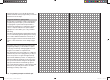
If your gyro features gain control from the transmitter -
unlike the type we are using in this example - you will
need another free proportional control for it, e. g. CTRL
8. This can be assigned to the “Gyro” input in the …
“Transmitter control settings” menu (page 76).
+
trv
free
ctrl 7
ctrl 8
thr
gyr
lim
+100%
+100%
+100%
+100%
+100%
+100%
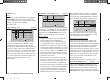
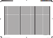
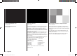
Turn the rotary control until its number (transmitter
control n
umber) appears on the screen, then use the
arrow button f of the left or right-hand four-way button
to move to the ASY fi eld in the “Travel” column. Briefl y
press the central SET button of the right-hand four-way
button, and you will be able to set a maximum gyro gain
such as 50% in the now highlighted fi eld:
+
+100%
+100%
+100%
+100%
+50% +50%
trv
free
ctrl 7
ctrl 8
thr
gyr
lim
This represents a safe fi xed value which is maintained
as long as the rotar
y control is at its right-hand end-stop.
You will probably need to adjust the value in the course
of fl ight-testing. Additional notes on setting up gyros can
be found on pages 98 / 99.
Further adjustments
If you have followed this programming example, you will
have a helicopter which is set up properly, and in an
ideal state for hovering practice and simple circuits. Of
course, you may wish to activate further functions de-
pending on your skill and fl ying experience. If you wish
to fl y using different rotor speeds and trim set-ups, you
will need to activate a series of “fl ight phases”, which
can be called up via switches which you assign. The fi rst
step in this process is to call up the …
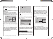
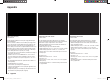
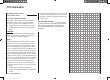
“Basic model settings” menu (pages 64 … 71)
pitch min
rear
timer 10:01 C3
phase 2 hover
autorotat.
3
7
rotor direct right
… assign a switch to “Phase 2”, e. g. SW 7, and enter a
rele
vant name (if you wish).
It is important to be quite clear in your mind that auto-
rotation always has absolute precedence over any
other phases. This simply means: if you operate the
auto-rotation switch, you immediately move to the auto-
rotation phase from either of the other two fl ight phases
(“normal” phase and “phase 2”).
Now move back to the “Helimix” menu, switch to “Phase
2” (which you have just set up), and modify the settings
accordingly. Since the mx-12 HoTT features digital
trims, in the Heli program all the trim positions for the
control functions “roll”, “pitch-axis” and “tail rotor” are
stored separately for each fl ight phase, in addition to the
other menu settings which you entered separately for
each fl ight phase (see page 94).
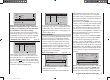
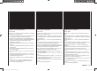
For example, if the motor run is limited by the fueltank
size or battery capacity, you should set the stopwatch
to count down. Enter the maximum possible motor
run time, e. g. “5 min.”. The transmitter’s sounder now
starts emitting warning sounds starting at “30 s” before
“zero”, as described on page 67 / 68. You could assign
the transmitter control switch “G3” to this timer, by fi rst
activating switch assignment and then turning the throt-
tle limit control from its idle position in the direction of
full-throttle:
rotor direct
swashplate
right
3sv(2rol)
cut off –100% +150%
1
pitch min
rear
timer
5:00 C3
With the stopwatch halted, press the cd or ef but-
tons of the left-hand four-way button (CLEAR) simul-
taneously at the basic display, so that the stopwatch
switches to the “Timer” function. The timer then starts
33112_mx12_HoTT_2_GB.indd Abs48:17133112_mx12_HoTT_2_GB.indd Abs48:171 06.06.2011 19:39:4806.06.2011 19:39:48