
User's Manual


32
Using the receiver for the fi rst time
Using the receiver for the fi rst time
Preliminary notes regarding the GR-12 receiver
For more information please visit the Internet at www.graupner.de.
Receiving system
The mx-12 HoTT radio control set includes a GR-12
2.4 GHz bi-directional receiver which is suitable for con-
nection to a maximum of six servos.
In order to create a connection to the transmitter, the
Graupner HoTT receiver must fi rst be “bound” to “its”
model memory in “its” Graupner HoTT transmitter; this
procedure is known as “binding”. However, binding is
only necessary once for each receiver / model memory
combination (see pages 61 or 70), and has already
been carried out at the factory for model memory 1
using the components supplied in the set. You therefore
only need to carry out the “binding” process with ad-
ditional receivers, or if you switch to a different model
memory. The procedure can also be repeated whenever
you wish - for instance, if you change the transmitter.
For this reason, if you connect the GR-12 HoTT receiver
supplied in the set to a power supply and switch it on,
the integral LED briefl y lights up green, and then goes
out again, assuming that “its” transmitter is not in range,
or is switched off. If a connection is made, the LED
glows a constant green.
Note:
If the LED glows a constant green, but the receiver
responds neither to the SET button nor to control com-
mands, then please check the polarity of your receiver
power supply.
Receiver voltage display
Once a telemetry connection exists, the actual voltage
of the receiver power supply is displayed on the right-
hand side of the transmitter screen.
Temperature warning
If the temperature of the receiver falls below a limit value
set on the receiver (the default is -10°C), or exceeds
the upper warning threshold, which is also set on the
receiver (the default is +70°C), the transmitter generates
a warning in the form of steady beeps at intervals of
about one second.
Firmware update
Fir
mware updates for the receiver are carried out using
the receiver’s telemetry socket - in the case of the GR-
12 receiver supplied as standard in the set this is servo
socket 5, which is also marked with a “T” - in conjunction
with a PC running Windows XP, Vista or 7. To connect
the receiver to a PC you require the separately available
USB interface, No. 7168.6 and the adapter lead, Order
No. 7168.6A. The latter - like all other connecting leads
- must always be connected to the GR-12 receiver with
the brown or black wire facing up.
The latest software and information can be found in the
Download area for the corresponding product at www.
graupner.de.
Note:
Once you have registered your transmitter at http://
graupner.de/de/service/produktregistrierung you will
automatically be informed of new updates by e-mail as
they become available.
Servo connections and polarity
The servo sockets of Graupner HoTT receivers are
numbered. The connector system is polarised: look for
the small chamfers when inserting the connectors, and
on no account force the plugs into the sockets.
The power supply is through-connected via all the num-
bered sockets. If there is no vacant servo socket, it is
also possible to connect the power supply via a Y-lead,
Order No. 3936.11, in parallel with a servo.
Do not connect the battery to these sockets with
reversed polarity, as this is likely to ruin the receiver
and any devices connected to it.
The function of each individual channel is determined by
the transmitter you are using, rather than by the receiver.
The throttle servo socket is defi ned by the radio control
system, and may differ according to the make and type.
For example, in the case of Graupner radio control
systems the throttle function is assigned to channel 1 for
fi xed-wing models, and channel 6 for helicopters.
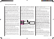
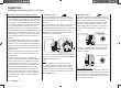
Servo socket 5: “SERVO” or “SENSOR”
The servo socket 5, which is marked with an additional
“T” …
Servo
sensor
OR
… can be used not only to update the receiver by con-
necting the adapter lead, Order No. 7168.6A, but also to
connect a telemetry sensor.
However, to ensure that the receiver correctly detects
the device connected to this socket, servo socket 5
MUST be reset from “SERVO” to “SENSOR” and vice
versa to suit the device. This is carried out in the “Te-
lemetry” menu on the “RX CURVE” page of the “SET-
TING & DATA VIEW” sub-menu. See the section starting
on page 118 for more details:
33112_mx12_HoTT_2_GB.indd Abs10:3233112_mx12_HoTT_2_GB.indd Abs10:32 06.06.2011 19:39:3506.06.2011 19:39:35