
User's Manual


38
Defi nition of terms
Defi nition of terms
Control functions, transmitter controls, function inputs, control channels, mixers, switches, control switches
To make it easier for you to understand the mx-12
HoTT manual, the following section contains defi nitions
of many terms which crop up again and again in the
remainder of the text.
Control function
The term “control function” can be thought of as the
signal generated for a particular function which needs
to be controlled - initially independent of its subsequent
progress through the transmitter. In the case of fi xed-
wing model aircraft the control functions include throttle,
rudder and aileron, whereas collective pitch, roll and
pitch-axis are typical of those used for helicopters. The
signal of a control function may be assigned directly, or
to several control channels simultaneously via mixers.
A typical example of the latter is separate aileron ser-
vos, or pairs of roll-axis or pitch-axis servos in a model
helicopter. The essential feature of a control function is its
infl uence on the mechanical travel of the corresponding
servo.
Transmitter control
The term “transmitter control” refers to the mechanical
elements on the transmitter which are operated directly
by the pilot. Their movements in turn generate corre-
sponding movements in the servos, speed controllers
etc. at the receiver end. The transmitter controls include
the following:
The two dual-axis stick units for the control functions •
1 to 4; for both model types (“fi xed-wing” and “helicop-
ter”) these four functions can be interchanged in any
way you wish using the “Mode” function, e. g. throttle
left or right, without having to re-connect the servos.
The dual-axis stick function for throttle (or airbrakes) is
often referred to as the Ch 1 (Channel 1) control.
The two rotary proportional controls CTRL 7 + 8•
The switches SW 4/5 and 6/7, and CTRL 9 and 10•
The switches SW 1 and 3, if they have been assigned •
to a control channel in the “Transmitter control
settings” menu.
When a proportional transmitter control is operated, the
servo or servos follow the position of the control directly,
whereas a switched channel provides just the two or
three set servo positions.
Function input
This is an imaginary point on the signal path, and must
not be considered the same as the point on the circuit
board where the transmitter control is connected! The
two menus “Stick mode” and “Transmitter control
settings” affect the course of the signal “after” this point,
and it is possible (and likely) that there will be differences
between the number of the transmitter control (as stated
above) and the number of the subsequent control chan-
nel.
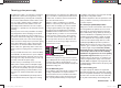
Control channel
There is a point on the signal path where the signal con-
tains all the control information required for a particular
servo – this may be directly generated by a transmitter
control or indirectly via a mixer – and from this point on
we call the signal a “control channel”. This signal is only
affected by any adjustments carried out in the “Servo
settings” menu before leaving the transmitter via the RF
module. Once picked up at the receiver, this signal may
be modifi ed by any settings made in the Telemetry menu
before fi nally passing to the corresponding servo in the
model.
Mixer
The transmitter’s software includes a wide range of mixer
functions. Their purpose is to enable a control function to
affect multiple servos at the branching point of the mixer
input, or alternatively to allow several control functions
to affect one servo. For more information please refer to
the numerous mixer functions as described in the section
starting on page 88 of the manual.
Switch
The standard toggle switch SW 3, the two three-position
switches SW 4/5 and 6/7 and the momentary button
SW 1 can also be incorporated into the programming of
the transmitter controls. However, all these switches are
also generally intended for switching program options,
e. g. starting and stopping timers, switching mixers on
and off, transferring control in Trainer mode etc. Each
physical switch function can be assigned to as many
functions as you wish. Numerous examples are de-
scribed in the manual.
Transmitter control switch
It is often desirable to switch a function on or off auto-
matically at a particular position of another transmitter
control, e. g. at a defi ned position of one of the dual-axis
sticks. Typical examples are switching a stopwatch on
and off to allow you to record the motor run time, extend-
ing spoilers automatically (and many others). The mx-
12 HoTT software includes a total of two (three - for
helicopters) “control switches” of this type.
Two transmitter control switches are available for the Ch
1 stick in each model memory, both for fi xed-wing model
aircraft and helicopters. For helicopters a third is present
in the form of the throttle limiter; see the right-hand side
and page 67.
This manual includes a range of instructive examples
which make programming as simple as child’s play.
Please refer to the programming examples in the section
starting on page 144.
33112_mx12_HoTT_2_GB.indd Abs12:3833112_mx12_HoTT_2_GB.indd Abs12:38 06.06.2011 19:39:3506.06.2011 19:39:35