
User's Manual


39
Assigning switches and control switches
Assigning switches and control switches
The basic procedure
At many points in the program there is the option of
using a switch (SW 1, 3 … 7) or a control switch (G1 …
3; see below) to operate a function, or to switch between
settings, such as the DUAL RATE / EXPO function, fl ight
phase programming, mixers and more. The mx-12
HoTT allows you to assign several functions to a single
switch.
The process of assigning switches is exactly the same
in all the relevant menus, and we will explain the basic
programming procedure at this point so that you can
concentrate on the special features when reading the
detailed menu descriptions.
A switch symbol appears in the bottom line of the screen
at all programming points where switches can be as-
signed:
Move to the appropriate column using the arrow buttons
of the left or right four-way button.
This is the procedure for assigning a switch:
Briefl y press the 1. SET button of the right-hand four-
w
ay button. The following message appears on the
screen:
push desired switch
into position ON
Now simply move the switch you wish to use to the 2.
“ON” position, press the push-button, or move the
Ch 1 stick from the “OFF” position in the direction of
“ON”. Please note: the so-called control switches as-
signed to this transmitter control (see right) carry out
the task of an ON / OFF switch in software; the same
applies to the throttle limiter (see page 79) which is
available in the “Helicopter” model type. This com-
pletes the assignment process.
Changing the direction of switching:
If the switch turns out to work in the wrong direction, you
can correct it as follows: move the switch to the desired
OFF position, activate switch assignment once more
and assign the switch again, this time with the switch
direction you prefer.
Erasing a switch:
Activate the switch symbol as described un-
der Point 2, then briefl y press the button combina-
tion cd or ef of the right-hand four-way button
(CLEAR) simultaneously.
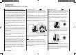
Transmitter control switches
Many functions are best controlled automatically by a
particular (freely programmable) position of the Ch 1
transmitter stick (or the throttle limiter in the case of heli-
copters), rather than by a conventional physical switch.
Typical applications:
Automatically switching an on-board glowplug ener-•
gizer on and off according to the throttle position of
the Ch 1 stick (“G1” or “G2”). In this case the switch
for the plug energizer is controlled by a mixer at the
transmitter.
Automatically switching a stopwatch on and off to •
record the pure “fl ight time” of a model helicopter; this
is accomplished using the “G3” switch of the throt-
tle limiter.
Automatically switching the “AIL • ¼ RUD” mixer off
when the airbrakes are extended, in order to keep
the wings parallel with the ground when landing on
a slope face, without the (usually coupled) rudder af-
fecting the model’s heading.
Automatically extending landing fl aps with coupled el-•
evator trim adjustment on the landing approach, as
soon as the throttle stick is reduced below the set
threshold point.
Automatically switching a stopwatch on and off in or-•
der to time the run of an electric motor.
For both model types the mx-12 HoTT transmitter’s
software caters for these purposes with two “control
switches” of this type; they can be assigned to the Ch 1
stick: “G1” is switched on at around -80% of full travel,
while “G2” is switched on at around +80%. The Helicop-
ter program also includes an extra control switch “G3” on
the throttle limiter close to the 100% point; see page 79.
All these control switches can be included without
restriction in the free programming of the switches, i. e.
they can be assigned to a function instead of a physical
switch. This means that you are able to assign one of
the control switches G1 … G2 (or G1 … G3) instead
of a physical switch at any point in the software where
switches are assigned. All you have to do is move the
Ch 1 stick or the throttle limiter control (by default the
rotary proportional control CTRL 7) from the desired
“OFF” position in the direction of “ON”.
33112_mx12_HoTT_2_GB.indd Abs14:3933112_mx12_HoTT_2_GB.indd Abs14:39 06.06.2011 19:39:3506.06.2011 19:39:35