
User's Manual


40
Digital trims
Digital trims
Description of function, and Ch 1 cut-off trim
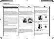
Digital trims with visual and audible indicators
Both the dual-axis stick units are fi tted with digital trim
systems. When you give the trim lever a brief push (one
“click”), the neutral position of the associated stick chan-
nel changes by one increment. If you hold the trim lever
in one direction, the trim value changes continuously in
the corresponding direction with increasing speed.
The degree of trim offset is also “audible”, as the pitch of
the tone changes to refl ect the setting. When you are fl y-
ing a model, you can fi nd the trim centre position easily
without having to look at the screen: if you over-run the
centre setting, the trim stays in the centre position for a
moment.
The current trim values are automatically stored when
you switch from one model memory to another. The dig-
ital trims are also stored separately for each fl ight phase
within a model memory, with the exception of the “Ch 1”
(Channel 1) trim, which is the throttle / airbrake trim on a
fi xed-wing model.
The Ch 1 trim includes another special function which
makes it easy to re-locate the idle throttle setting of a
glowplug motor.
However, since the trim functions described in these
instructions only affect the “Motor off” direction, the trim
display on the transmitter’s screen will vary according
to your individual set stick mode, i. e. the “forward” or
“back” throttle / collective pitch minimum position of the
Ch 1 stick, and also according to “left stick” or “right
stick” for throttle / collective pitch. The illustrations in
these instructions always refer to “Throttle / Collective
pitch right” for both model types, and to “Throttle back”
for fi xed-wing models and “Collective pitch forward” for
model helicopters.
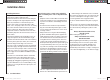
2. Model helicopters
In helicopter mode the Ch 1 trim has another feature in
addition to “cut-off trim”, as described under “Fixed-wing
models” on the left; this time in conjunction with the
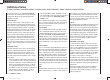
“Throttle limit function” (see page 79): while the throttle
limit slider is in the bottom half of its travel, i. e. in the
“start-up range”, the Ch 1 trim lever acts as idle trim on
the throttle limit, and the idle trim is displayed on the
screen:
GRAUBELE
#01
3:33h
stop
flt
K78
0:00
0:00
RX0.0V
50%
5.2V
2.4
M
CTRL 7
Current trim position
Trim at motor OFF position
Last idle position
Throttle limit control
In contrast to a fi xed-wing model aircraft, this display is
suppressed if the throttle limit control is moved to the
“right” half of its travel.
GRAUBELE
#01
3:33h
stop
flt
K78
0:00
0:00
RX0.0V
50%
5.2V
M
2.4
CTRL 7
Throttle limit control
Note regarding helicopters:
The Ch 1 trim only affects the throttle servo and not the
collective pitch servos; it also works evenly over the full
stick travel. Please note that the helicopter throttle servo
must be connected to receiver output 6 (see Receiver
socket assignment, page 47).
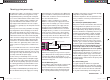
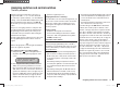
1. Fixed-wing models
The Ch 1 trim features a special cut-off trim which is
designed for glowplug motors: you initially use the trim
lever in the usual way to select a reliable idle setting for
the motor.
If you now move the Ch 1 trim lever to its end-point in
the direction of “motor cut-off”, pushing the lever in a
single movement, a marker appears on the screen in the
last position. You can now return to the idle setting for
starting the motor simply by pushing the stick one click
in the direction of “open throttle”.
GRAUBELE
#01
3:33h
stop
flt
K78
0:00
0:00
RX0.0V
50%
5.2V
Current trim position
2.4
M
Trim at motor OFF position
Last idle position
Idle direction
Ch 1 trim lever
The cut-off trim feature is disabled if you enter “none” or
“none / inv” in the “Motor at Ch 1” line within the “Basic
settings” menu (page 56 / 57).
Note:
Since this trim function is only effective in the “Mo-
tor off” direction, the above illustration will not apply if
you change the direction of the Ch 1 stick for throttle
minimum from “back” (which is refl ected in the illustra-
tion above) to “forward” in the “Motor at Ch1” line of the
“Basic settings” menu.
33112_mx12_HoTT_2_GB.indd Abs15:4033112_mx12_HoTT_2_GB.indd Abs15:40 06.06.2011 19:39:3506.06.2011 19:39:35