
User's Manual


42
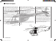
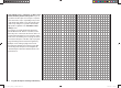
Fixed-wing model aircraft
Fixed-wing model aircraft
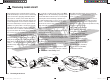
This program provides convenient support for normal
model aircraft with up to two aileron servos and two fl ap
servos, V-tail models, fl ying wings and deltas with two
elevon (aileron / elevator) servos and two fl ap servos.
The majority of power models and gliders belong to the
“normal” tail type with one servo each for elevator, rud-
der, ailerons and throttle or electronic speed controller
(airbrakes on a glider). There is also the special model
type “2 EL Sv” which provides a means of connecting
two elevator servos to channels 3 and 6 in parallel.
If your model features two separate aileron servos (and
also in some cases two fl ap servos), the aileron travel of
both pairs of control surfaces can be set up with dif-
ferential movement in the “Wing mixers” menu, i. e. the
down-travel can be set independently of the up-travel.
Finally the program caters for camber-changing fl aps,
which can be operated by any of the transmitter controls
“CTRL 7 … 10”. Alternatively a phase-specifi c trim is
available for fl aps, ailerons and elevator in the “Phase
trim” menu.
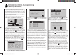
If the model features a V-tail instead of a conventional
tail, you need to select the tail type “V-tail” in the “Basic
settings” menu, as this automatically superimposes the
elevator and rudder control functions in such a way that
each tail panel can be actuated by a separate servo.
For deltas and fl ying wings it is easy to set up mixed
elevons, i. e. the aileron and elevator functions can be
carried out via common control surfaces at the trailing
edge of the right and left wing. As standard the program
contains the appropriate mixer functions for the two
servos.
Up to three fl ight phases can be programmed in each of
the ten model memories.
The digital trim positions are stored separately for each
fl ight phase, with the exception of the Ch 1 trim. The Ch
1 trim provides a simple means of re-locating the correct
idle throttle setting.
Two timers are available at all times when fl ying. The
screen also displays the transmitter operating time since
the battery was last charged.
All the transmitter controls (CTRL) and switches (SW)
can be assigned to virtually any of the inputs 5 and 6 in
the “Transmitter control settings” menu.
“Dual Rate” and “Exponential” can be programmed
separately for aileron, rudder and elevator, giving two
modes of control.
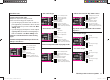
Depending on the model type you have selected, the
“Wing mixers” menu presents you with up to twelve
additional pre-defi ned mixers and coupling functions
which you can simply select and set up when necessary,
in addition to three free mixers:
1. Aileron differential (switchable)
2. Flap differential (switchable)
3. Aileron ¼ rudder (switchable)
4. Aileron ¼ fl ap (switchable)
5. Airbrake ¼ elevator (switchable)
6. Airbrake ¼ fl ap (switchable)
7. Airbrake ¼ aileron (switchable)
8. Elevator ¼ fl ap (switchable)
9. Elevator ¼ aileron (switchable)
10. Flap ¼ elevator (switchable)
11. Flap ¼ aileron (switchable)
12. Differential reduction
A
i
l
e
r
o
n
R
u
d
d
e
r
E
l
e
v
a
t
o
r
A
i
l
e
r
o
n
left
right
E
l
e
v
a
t
o
r
F
l
a
p
F
l
a
p
E
l
e
v
a
t
o
r
A
i
l
e
r
o
n
R
u
d
d
e
r
A
i
l
e
r
o
n
F
l
a
p
Airbrake
Flap
Airbrake
Elevator
Airbrake-Function 1
left
right
Rudder/Elevator
V-Tail
E
l
e
v
a
t
o
r
A
i
l
e
r
o
n
A
i
l
e
r
o
n
R
u
d
d
e
r
F
l
a
p
E
l
e
v
a
t
o
r
E
l
e
v
a
t
o
r
F
l
a
p
A
i
l
e
r
o
n
F
l
a
p
F
l
a
p
A
i
l
e
r
o
n
F
l
a
p
A
i
l
e
r
o
n
A
i
l
e
r
o
n
F
l
a
p
Airbrake Flap
Airbrake
Elevator
Airbrake
Aileron
33112_mx12_HoTT_2_GB.indd Abs16:4233112_mx12_HoTT_2_GB.indd Abs16:42 06.06.2011 19:39:3606.06.2011 19:39:36