
User's Manual


47
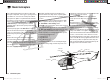
Model helicopters: receiver assignment
Note for modellers upgrading from earlier Graupner
systems:
Compared with the previous receiver channel sequence,
servo socket 1 (collective pitch servo) and servo socket
6 (throttle servo) have been interchanged. The servos
must be connected to the receiver output sockets in the
order shown at bottom right. Outputs not required are
simply left vacant. For more information on the different
types of swashplate, please refer to the “Basic settings”
menu described on page 64 / 65.
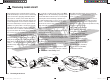
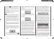
Installation notes
The servos MUST be connected to the receiver
outputs in the order shown on this page:
Outputs not required are simply left vacant.
Please note the additional information on the follow-
ing pages.
Note:
To be able to exploit all the convenience and safety
features of the throttle limiter (see section starting on
page 79), the speed controller should be connected to
receiver output “6”. See page 96 for more details.
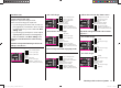
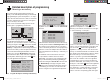
Receiver assignment for model helicopters …
… with one to three swashplate servos
Throttle or speed governor
Tail rotor servo (gyro system)
Roll 1 servo
Pitch-axis 1 servo
Telemetry sensor or gyro gain
Receiver power supply
Receiver power supply
Collective pitch or roll 2
or pitch-axis 2 servo
… with four swashplate servos
Throttle or speed governor
Tail rotor servo (gyro system)
Roll 1 servo
Pitch-axis 1 servo
Pitch-axis 2 servo
Receiver power supply
Receiver power supply
Roll 2 servo
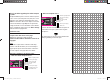
All menus which are relevant to model helicopters are
marked with a “helicopter” symbol in the “Program
descriptions”:
This means that you can easily skip irrelevant menus
when programming a model helicopter.
33112_mx12_HoTT_2_GB.indd Abs20:4733112_mx12_HoTT_2_GB.indd Abs20:47 06.06.2011 19:39:3606.06.2011 19:39:36