
User's Manual

58
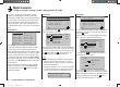
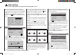
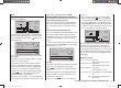
Program description: base settings - fi xed-wing model
mod name
stick mode
motor at C1
1
idle re.
tail type normal
GRAUBELE
cut off +100%
STO
–125% 1
tail type
mod name
stick mode
motor on C1
1
idle re.
tail type normal
GRAUBELE
cut off +100%–125% 1
When you select “tail type” using the arrow buttons cd
of the left or right-hand four-way button, you will see the
corresponding input fi eld framed. Press the central SET
button of the right-hand four-way button to highlight the
current setting. Now use the arrow buttons of the right-
hand four-way button to select the option which matches
your model:
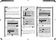
„normal“: This setting caters for all models in which
each of the functions ele
vator and rudder
is operated by one servo.
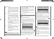
„V-tail“: The elevator and rudder functions are
operated by two control surfaces set in a
V-shape, each controlled by a separate
servo. The two-way coupling function for
the rudder and elevator control systems
is automatically carried out by the trans-
mitter software. If necessary, the ratio
of rudder travel to elevator travel can be
adjusted in the “Dual Rate” menu (page
82).
„Delt/FlW“: The mixed elevon (aileron and eleva-
tor) control system requires two or four
separate servos, one or two in each wing.
However, the elevator trim only affects
servos 2 + 3, even if you select “2ail2fl ” -
see below.
„2elev sv“: This option is designed for model aircraft
with one or two aileron servos and two
elevator servos. When the elevator stick
is moved, the servo connected to receiver
output 6 moves in parallel with servo 3.
The elevator trim lever affects both ser-
vos.
Note regarding “2elev sv”:
In this mode a tr
ansmitter control which
is assigned to input 6 in the “Transmitter
control settings” menu is de-coupled
from servo “6”; this is for safety reasons.
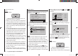
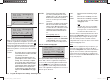
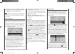
Ailerons / Camber-changing fl aps
stick mode
motor at C1
1
idle re.
tail type normal
cut off +100%–125% 1
aile/flap 1aile
When you select the “Aileron / Flap” line using the arrow
b
uttons cd of the left or right-hand four-way button,
you will see the corresponding input fi eld framed. Press
the central SET button of the right-hand four-way but-
ton to highlight the current setting. Now use the arrow
buttons of the right-hand four-way button to select one of
the three options, which are.
“1aile” Both ailerons are actuated by a single
servo.
“2aile” Each aileron is actuated by one servo.
“2ail2fl ” Each aileron is actuated by a separate
servo; there are also one or two camber-
changing fl ap servos.
Note:
The
“2AL 2FL” option is only available
with the tail types “normal” and “V-tail”,
and only if “none” or “none/inv” has been
selected in the “Motor at Ch 1” line.
The mixers and associated adjustment facilities which
appear in the “Wing mixers” menu (see section start-
ing on page 88) vary according to the data you enter
here. The software provides a maximum of twelve
ready-made mixers for up to two aileron servos and two
camber-changing fl ap servos.
Note:
If your model is equipped with only one fl ap servo, you
should still select “2ail2fl ”, but leave the “AIL ¼ FL”
mixer in the “Wing mixer” menu, which is described on
page 91, at 0%. In contrast, all the other wing mixers
can be used in the usual way. The second fl ap socket
which is now “vacant” must ON NO ACCOUNT be used
for any other purpose!
33112_mx12_HoTT_2_GB.indd Abs24:5833112_mx12_HoTT_2_GB.indd Abs24:58 06.06.2011 19:39:3706.06.2011 19:39:37