
User's Manual

60
Program description: base settings - fi xed-wing model
The “alarm timer” is reset by simultaneously pressing
the cd or ef buttons of the right-hand four-way but-
ton (CLEAR), once you have halted the timer.
Note:
A count-down timer is indicated in the basic display by
a fl ashing colon (:) between the minutes fi eld and the
seconds fi eld.
Phase 2 and Phase 3
You will automatically be in the “normal” fl ight phase 1
unless you have already assigned a switch to phases 2
or 3.
Both the number and name of this fl ight phase are fi xed
permanently as “normal”, and cannot be changed. For
this reason the “normal” phase is simply concealed, i. e.
it is not displayed as phase 1.
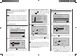
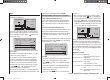
10:01 3
phase 2
phase 3
takeoff
speed
–––
–––
aile/flap 2aile
timer
tail type normal
It is also important to understand that the fl ight phases
ha
ve their own inherent priorities which need to be ob-
served, particularly when assigning individual switches.
The underlying scheme can be described as follows:
If all assigned fl ight phase switches are closed or •
open, the “normal” fl ight phase is active.
If only one switch is closed, then the fl ight phase as-•
signed to the currently closed switch is active.
If two switches are closed, then the fl ight phase with •
the lower phase number is active.
For example, this would be phase 2 if the switch as-
signed to phase 3 is also closed.
As a result you may wish to take the inherent phase •
priorities into account when assigning names to the
fl ight phases; see below.
At the servo end the transition does not occur •
“abruptly”, but with a fi xed transition period of about
one second.
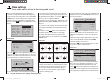
Programming
When you select “phase 2” or “phase 3” using the arrow
buttons cd of the left or right-hand four-way button,
the “Name” fi eld for that fl ight phase is already framed.
If the default name does not seem appropriate, press
the central SET button of the right-hand four-way button,
and the current setting is sho
wn highlighted. Now use
the arrow buttons of the right-hand four-way button to
select an appropriate name from those available. Press
the SET button to conclude the input process.
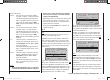
Now press the f button of the left or right-hand four-
way button to move to the right-hand column at the bot-
tom of the screen, indicated by the switch symbol
,
and briefl y press the central SET button. You can now
assign a switch to the phase as described on page 39.
We recommend one of the two three-position switches
SW 4/5 or SW 6/7, in each case starting from the centre
toggle position.
For more information on fl ight phase programming
please refer to page 86, in the section entitled “Phase
trim”.
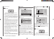
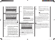
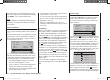
Receiver output
For maximum fl exibility in terms of receiver socket
assignment, the mx-12 HoTT software provides the
means to swap over the servo outputs 1 to max. 6;
this is carried out on the second page of the “Receiver
output” sub-menu.
10:01 3
phase 2
phase 3
takeoff
speed
timer
7
6
receiv out
aile/flap 2aile
Press the central SET button of the right-hand four-way
b
utton to move to the next page of the display. Here you
can assign the “control channels” for servos 1 … 6 to
any receiver output you wish to use. However, please
note that the display in “Servo display” - which you can
access from virtually any menu position by simultane-
ously pressing the e and f buttons of the left-hand
four-way button - refers exclusively to the “control chan-
nels”, i. e. the outputs are NOT swapped over.
S
S
S
S
1
2
3
4
1
2
3
4
output
S
5
5
output
output
output
output
Use the arrow buttons cd of the left or r
ight-hand four-
way button to select the servo / output combination you
wish to change, then press the central SET button of
the right-hand four-way button. Now you can assign the
desired servo (S) to the selected output using the right-
33112_mx12_HoTT_2_GB.indd Abs24:6033112_mx12_HoTT_2_GB.indd Abs24:60 06.06.2011 19:39:3806.06.2011 19:39:38