
User's Manual


67
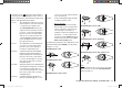
Program description: base settings - model helicopter
right-hand
rotation
left-hand
rotation
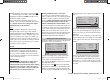
The program requires this information in order to set up
the mixers to work in the correct “sense”; this applies to
the mixers which compensate for rotor torque and motor
power. You will fi nd these in the “Helicopter mixer”
menu:
Pitch
Ch1 ¼ throttle
Ch1 ¼ tail rotor
Collective pitch min.
stick mode
rotor direct
swashplate
1
right
3sv(2rol)
cut off –125% +100%
1
pitch min
rear
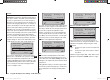
In the “Collective pitch min.” line you can set up the
direction of oper
ation of the throttle / collective pitch
stick to suit your preference. This setting is crucial to the
correct operation of all the other options in the helicopter
program which affect the throttle and collective pitch
functions, i. e. the throttle curve, idle trim, tail rotor mixer
etc.
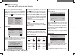
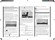
Press the central SET button of the right-hand four-way
button, and the direction of operation of the throttle /
collective pitch stick is highlighted. Now you can select
the required variant using the arrow buttons of the right-
hand four-way button:
Pitch
The meaning is as follows:
“front”: minimum collective pitch when the collective
pitch stick (Ch 1) is “forward” (away from you);
“rear”: minimum collective pitch when the collective
pitch stick (Ch 1) is “back” (towards you).
Simultaneously pressing the cd or ef buttons of the
right-hand four-way button (CLEAR) returns the collec-
tive pitch min. position to “rear”.
Note:
The Ch 1 trim always affects the throttle servo only.•
By default what is known as the “throttle limiter” is set •
(see page 79); this limits the travel of the throttle ser-
vo in the direction of maximum throttle, acting sepa-
rately from the collective pitch servos. This point can
be programmed using the “Lim” input in the “Trans-
mitter control settings” menu.
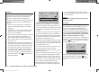
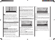
Timers
Two timers are shown in the basic display: one stop-
watch and one fl ight timer.
STARLET
#02
0:00h
stop
flt
K78
0:00
0:00
0.0V
6.1V
HoTT
M
99%
A physical switch or a control switch - e. g. the control
switch G3 located on the throttle limiter - can be as-
signed to these two timers in the “Timers” line …
rotor direct
swashplate
right
3sv(2rol)
cut off
–125%
+100%
1
pitch min
rear
timer 0:00 –––
… using the switch symbol at the bottom right-hand
side of the screen. The assigned switch starts both tim-
ers, and also halts the stopwatch.
The method of assigning a physical switch or a control
switch is described on page 39.
The fl ight timer, and the saving of telemetry data on a
memory card inserted in the card slot (see page 22)
always starts simultaneously with the stopwatch, but
continues to run even when the stopwatch is halted
(switched off). It can only be stopped by pressing the
central ESC button of the left-hand four-way button with
the stopw
atch halted.
Once stopped, both timers can be reset to the initial
value by simultaneously pressing the cd buttons of
33112_mx12_HoTT_2_GB.indd Abs25:6733112_mx12_HoTT_2_GB.indd Abs25:67 06.06.2011 19:39:3806.06.2011 19:39:38