
User's Manual


68
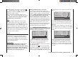
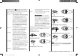
Program description: base settings - model helicopter
the right-hand four-way button (CLEAR).
Switching between “count-up” and “count-down”
Count-up timer (stopwatch function)
If you assign a switch and start the stopwatch with the
initial value of “0:00”, the timer runs up until the maxi-
mum of 180 minutes and 59 seconds, then re-starts at
0:00.
Count-down timer (timer function)
In the left-hand minutes fi eld you can select a starting
time within the range 0 to 180 minutes; in the right-hand
seconds fi eld the range is 0 to 59 seconds. Any combi-
nation of times can also be selected.
Simultaneously pressing the cd buttons of the right-
hand four-way button (CLEAR) resets any settings you
have entered to “0” or “00”.
rotor direct
swashplate
right
3sv(2rol)
cut off
–125%
+100%
1
pitch min
rear
timer 10:01
G3
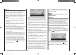
Procedure
Select the desired input fi eld using the arrow buttons 1.
ef of the left or right-hand four-way button.
Press 2. SET in the centre of the right-hand four-way
b
utton.
Select the required time in the highlighted minutes 3.
and seconds fi elds using the arrow buttons of the
right-hand four-way button.
Press the central 4. SET button to conclude the input
process
.
Switch back to the basic display by repeatedly press-5.
ing the central ESC button of the left-hand four-way
button. With the stopwatch halted, press the cd
buttons of the right-hand four-way button simultane-
ously (CLEAR) to switch the stopwatch to the “Timer”
function; see top right in the next illustration:
STARLET
#02
0:00h
stop
flt
K78
10:01
0:00
0.0V
6.1V
HoTT
M
99%
If you now operate the assigned switch, the stopwatch
starts from the set initial value, counting down (“Timer
function”). When the set time has elapsed, the timer
does not stop, but continues to run to allow you to read
off the time elapsed after reaching zero. To make this
clear, the over-run time is shown highlighted (black
background).
Sequence of sounds
30 sec. before zero: triple beep
single beep every two seconds
20 sec. before zero: double beep
single beep every two seconds
10 sec. before zero: single beep
single beep every second
5 sec. before zero: single beep every second at higher
rate
zero: longer beep; display switches to
inverse video
The “alarm timer” is reset by simultaneously pressing
the cd or ef buttons of the right-hand four-way but-
ton (CLEAR) after you have halted the timer.
Note:
A count-down timer is indicated in the basic display by
a fl ashing colon (:) between the minutes fi eld and the
seconds fi eld.
Phase 2
You will automatically be in the “normal” fl ight phase 1
unless you have already assigned a switch to phase 2 or
auto-rotation.
Both the number and name of this fl ight phase are fi xed
permanently as “normal”, and cannot be changed. For
this reason the “normal” phase is simply concealed, i. e.
it is not displayed as phase 1.
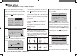
10:01 G3
phase 2 hover –––
rotor direct right
pitch min
rear
timer
cut off
–125%
+100%
1
It is also important to understand that the fl ight phases
have their own inherent priorities which need to be ob-
served, particularly when assigning individual switches.
The underlying scheme can be described as follows:
If all assigned fl ight phase switches are closed or •
open, the “normal” fl ight phase is active.
If only one switch is closed, then the fl ight phase as-•
signed to the currently closed switch is active.
The “auto-rotation phase” ALWAYS has precedence •
over all other fl ight phases, regardless of the priori-
ties outlined above. When the auto-rotation phase
is selected, the switch is always made WITHOUT
DELAY.
33112_mx12_HoTT_2_GB.indd Abs25:6833112_mx12_HoTT_2_GB.indd Abs25:68 06.06.2011 19:39:3806.06.2011 19:39:38