
User's Manual

72
Program description: servo settings
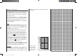
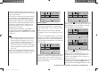
Column 3 “Centre”
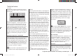
The facility to offset the servo travel centre is intended
for adjusting servos whose centre setting is not standard
(servo centre point at 1.5 ms or 1500 µs), and also for
minor adjustments, e. g. when fi ne-tuning the neutral
position of the model’s control surfaces.
The neutral position can be shifted over the range
-125% to +125% of normal servo travel, within the
maximum servo travel of +/- 150%, regardless of the
trim lever position and any mixers you have set up. The
setting affects the associated servo directly, independ-
ently of all other trim and mixer settings.
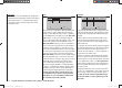
However, please note that an extreme shift of the servo’s
neutral point may result in servo travel to one side of
neutral only, as total servo travel is limited to +/- 150%
for both electronic and mechanical reasons.
Simultaneously pressing the arrow buttons cd or ef
of the right-hand four-way button (CLEAR) resets the
value in the highlighted input fi eld to “0%”.
S
e
r
v
o
t
r
a
v
e
l
-
1
2
5
%
C
e
n
t
r
e
a
d
j
u
s
t
m
e
n
t
+
1
2
5
%
receiver output socket to which a particular servo(s) is
connected, assuming that these have not been swapped
over. This means that changing the stick mode does not
affect the numbering of the servos.
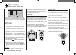
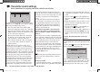
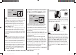
Column 2 “Rev.”
The direction of servo rotation can be adjusted to suit
the actual installation in your model. This means that
you don’t need to concern yourself with servo directions
when installing the mechanical linkages in the model,
as you can reverse them as and when necessary. The
direction of rotation is indicated by the symbols “=>” and
“<=”. Be sure to set the direction of servo rotation before
you make adjustments to the remaining options!
Simultaneously pressing the arrow buttons cd or ef
of the right-hand four-way button (CLEAR) resets the
direction of rotation to “=>”.
normal
reversed
normal
reversed
S1
S2
S3
rev cent
+
trav
0%
0%
0%
100%
100%
100%
100%
100%
100%
0%
0%
100%
100%
100%
100%
S4
S5
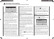
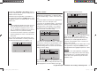
In this menu you can adjust parameters which only af-
fect the servo connected to a particular receiver output,
namely the direction of servo rotation, neutral point and
servo travel. Always start with the servo setting in the
left-hand column.v
Basic procedure:
Use the arrow buttons 1. cd of the left or right-hand
four-way button to select the relevant servo (1 to 6).
If necessary, use the arrow buttons 2. ef of the left or
right-hand four-way button to select the desired co-
lumn, and move the associated transmitter control
away from its centre position if you wish to defi ne an
asymmetrical setting.
Press the central 3. SET button of the right-hand four-
w
ay button, and the corresponding input fi eld is high-
lighted (black background).
Set the appropriate value using the arrow buttons of 4.
the right-hand four-way button.
Press the central 5. SET button of the right-hand four-
w
ay button to conclude the input process.
Simultaneously pressing the arrow buttons 6. cd or
ef of the right-hand four-way button (CLEAR) re-
sets any settings you have entered to the default val-
ue.
Important:
The numbers in the servo designations refer to the
Servo settings
Servo direction, centre, travel
33112_mx12_HoTT_2_GB.indd Abs26:7233112_mx12_HoTT_2_GB.indd Abs26:72 06.06.2011 19:39:3906.06.2011 19:39:39