
User's Manual

74
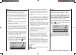
Program description: transmitter control settings - fi xed-wing model
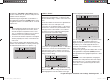
Transmitter control settings
Basic procedures for assigning transmitter controls and switches
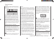
I5
I6
+
trv
+100%
+100%
+100%
+100%
free
free
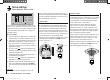
In addition to the two dual-axis stick units for the control
functions 1 to 4, the mx
-12 HoTT is fi tted as standard
with a range of supplementary controls:
Two rotary proportional controls: CTRL 7 and 8. •
These are included in the menu as “ctrl 7” and “ctrl 8”.
Two three-position switches: SW 4/5 or CTRL 9 and •
SW 6/7 or CTRL 10. These are assigned in this menu
as “ctrl 9” and “ctrl 10” respectively.
One two-position switch: SW 3. This is indicated in •
the menu by “3” plus a switch symbol, which indi-
cates the direction of operation of the switch.
One momentary switch: SW 1. This is indicated by •
“1” plus a switch symbol and direction indicator, as
mentioned above.
The two dual-axis stick units directly affect the servos
connected to receiver outputs 1 … 4 (assuming that you
have set up a newly initialised model memory with the
model type “Fixed-wing model”). In contrast, the “sup-
plementary” transmitter controls listed above are inactive
when the transmitter is in its default state (as delivered).
As already mentioned on page 20, this means that the
transmitter in its basic form only controls servos con-
nected to receiver outputs 1 … 4 using the primary
sticks - even when you have initialised a new model
memory with the model type “Fixed-wing model” and
“bound” it to the receiver you intend to install. Any ser-
vos connected to receiver sockets 5 and 6 simply stay
at their centre point when you operate the associated
transmitter controls.
This may seem rather inconvenient at fi rst sight, but
it is the only way to ensure that you can select any of
the “supplementary” transmitter controls for any task
you like, and that you are not required deliberately to
“program away” the transmitter controls which are not
required for a particular model.
Any superfl uous transmitter control will have an
effect on your model if you operate it by mistake -
unless it is inactive, i. e. unless no function is assi-
gned to it.
That is why you can select these “supplementary” trans-
mitter controls with complete freedom in the “Transmitter
control settings” menu and assign them to any function
input (see page 38) you like, as this method ensures
that the transmitter meets your own requirements
exactly. This also means that each of these transmitter
controls can be assigned to several functions simulta-
neously. For example, the same toggle switch SW X,
which you assign to an input in this menu, can also be
assigned as the On / Off switch controlling the “Timers”
in the “Basic settings” menu.
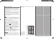
The basic procedure:
Select the appropriate input I5 … I6 using the arrow 1.
buttons cd of the left or right-hand four-way button.
If necessary, use the arrow buttons 2. ef of the left
or right-hand four-way button to switch to the desired
column.
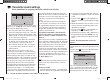
Press the central 3. SET button of the right-hand four-
w
ay button, and the corresponding input fi eld is high-
lighted.
Operate the transmitter control you wish to use, and 4.
set the desired value using the arrow buttons of the
right-hand four-way button.
Press the central 5. SET button of the right-hand four-
w
ay button to conclude the input process.
Simultaneously pressing the 6. cd or ef buttons of
the right-hand four-way button (CLEAR) resets any
settings you have entered to the appropriate default
value.
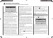
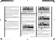
Column 2 “Assigning transmitter controls and
switches”
Select one of the function inputs 5 to 6 using the cd
buttons of the right-hand four-way button.
Press the central SET button of the right-hand four-way
b
utton to activate the assignment facility.
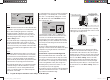
I5
E6
E7
+
trv
100%
100%
100%
100%
free
++
+
+
frei
frei
+100%
+100%
operate desired
switch or control
Now move the appropriate transmitter control (CTRL
7 to 10), or oper
ate the selected switch (SW 1 and 3).
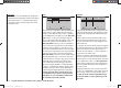
Note that the rotary proportional controls are not detect-
ed until they have moved a few “ratchet clicks”, i. e. they
need to be operated for slightly longer. If the travel is not
suffi cient for the transmitter to detect it, move the control
in the opposite direction.
If you assign one of the two-position switches, then this
control channel works like an On / Off switch. It is then
possible to switch to and fro between two end-point
values using this simple switch, e. g. motor ON / OFF.
The three-position switches SW 4/5 and 6/7, which you
33112_mx12_HoTT_2_GB.indd Abs27:7433112_mx12_HoTT_2_GB.indd Abs27:74 06.06.2011 19:39:3906.06.2011 19:39:39