
User's Manual

77
Program description: transmitter control settings – model helicopter
+
3
+100%
+100%
+100%
+100%
+100%
+100%
trv
free
ctrl 7
thr
gyr
lim
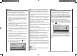
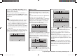
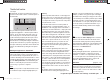
Press the central SET button of the right-hand four-way
b
utton to activate the value setting; the value fi eld is now
shown highlighted. Use the arrow buttons of the right-
hand four-way button to alter the values:
+
+111%
+111%
+100%
+100%
+100%
+100%
trv
free
ctrl 7
thr
gyr
lim
3
+
+88%
+100%
+100%
+100%
+100%
+111%
trv
free
ctrl 7
thr
gyr
lim
3
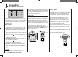
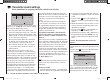
Press the central SET button of the right-hand four-way
button to conclude the input process.
Negative and positive parameter values are possible;
this enables you to set the appropriate direction of
movement of the transmitter control or its direction of
effect to suit your model.
Simultaneously pressing the arrow buttons cd or ef
of the right-hand four-way button (CLEAR) resets the
altered parameter in the highlighted input fi eld to +100%.
need to be operated for slightly longer. If the travel is not
suffi cient for the transmitter to detect it, move the control
in the opposite direction.
If you assign one of the two-position switches, then this
control channel works like an On / Off switch. It is then
possible to switch to and fro between two end-point
values using this simple switch, e. g. motor ON / OFF.
The three-position switches SW 4/5 and 6/7, which you
will fi nd in the “Transmitter control settings” menu as
“CTRL 9” and “CTR 10”, provide a centre position in
addition to the two end-points.
Simultaneously pressing the cd or ef buttons of
the right-hand four-way button (CLEAR) with the switch
assignment activated - see illustration above - resets the
input to “free”.
Tips:
When assigning the switches please take care to set •
them to the appropriate direction of travel, and en-
sure that all inputs not required are left at or set to
“free”, to eliminate the possibility of errors if unused
transmitter controls are operated accidentally.
You can alter the effective end-points of an assigned •
switch by adjusting servo travel as described in the
next section.
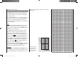
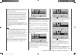
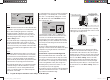
The screen now displays either the transmitter control
number or the switch number, followed by a switch sym-
bol which indicates the direction of operation, e. g.:
+
trv
free
ctrl 7
thr
gyr
lim
3
+100%
+100%
+100%
+100%
+100%
+100%
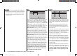
Column 3 “-Travel+”
In this column the tr
ansmitter control can be adjusted
symmetrically or asymmetrically, i. e. different to either
side. The available range is +/-125% of the normal servo
travel.
Use the arrow buttons cd of the left or right-hand
four-way button to select one of the inputs gyro, throttle
or lim.
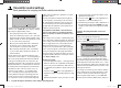
If you wish to set up symmetrical travel, i. e. the same in
both directions, move the associated transmitter control
(rotary proportional control or switches 4/5 and 6/7) to a
position at which the marking frame encloses both sides
of the travel setting:
+
3
+100%
+100%
+100%
+100%
+100%
+100%
trv
free
ctrl 7
thr
gyr
lim
If you wish to set up asymmetr
ical travel, i. e. different for
both directions, move the associated transmitter control
(rotary proportional control or switch) to a position at
which the marking frame encloses the side of the travel
setting you wish to change:
33112_mx12_HoTT_2_GB.indd Abs28:7733112_mx12_HoTT_2_GB.indd Abs28:77 06.06.2011 19:39:3906.06.2011 19:39:39