
User's Manual

79
Program description: transmitter control settings – model helicopter
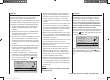
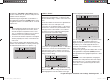
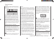
By default the “lim” input is assigned to the rotary pro-
portional control CTRL 7, which is located at top left on
the transmitter:
+
+100%
+100%
+100%
+100%
+100%
+100%
trv
free
ctrl 8
ctrl 7
thr
gyr
lim
This pre-defi ned assignment eliminates the need to
prog
ram two fl ight phases - “with idle-up” and “without
idle-up” - as are often used by other radio control sys-
tems for this purpose, since the method of raising the
system rotational speed below the hover point is more
fl exible with the mx-12 HoTT program, and can be
fi ne-tuned more accurately than using the conventional
“idle-up” function. However, if you prefer to program your
helicopter “with idle-up”, then switch off the “throttle limit”
function, described below, by setting the “Lim” input to
“free”.
Meaning and application of “throttle limit”
As mentioned previously under “Throttle”, the power
output of the engine or motor of a model helicopter is
not controlled directly using the throttle (Ch 1) stick - in
contrast to fi xed-wing model aircraft. Instead it is control-
led indirectly by the throttle curve settings which you set
up in the “Helicopter mixers” menu. Alternatively the
throttle is controlled by the speed controller if the unit
you are using is a governor or regulator.
Note:
Naturally it is possible to set up different throttle curves
to suit different stages of fl ight using fl ight phase pro-
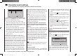
Throttle limit function
“Lim” input
gramming.
By their very nature, both methods of controlling power
have the same result, i. e. that a helicopter’s motor never
gets anywhere near its idle speed during “normal” fl ying,
so it is impossible to start or stop the motor easily unless
some other means is used.
The “Throttle limiter” function solves this problem in
an elegant manner: a separate transmitter control - as
standard this is the rotary proportional control CTRL 7
located at top left on the transmitter - is employed to limit
the setting of the throttle servo or the speed controller,
which means that you can throttle right back to the idle
position. At this setting the trim of the throttle / collective
pitch stick assumes control, and can be used to switch
off an electric motor directly. At the other extreme, the
throttle servo or speed controller can, of course, only
reach its full-throttle position if you release full servo
travel using the throttle limit control. That is why the
“lim” input is reserved in the Helicopter program for the
“Throttle limiter” function.
For this reason the right-hand positive value in the
“Travel” column must be large enough to ensure that it
does not limit the full-throttle setting available via the
throttle curve settings when the throttle limit control is at
its maximum position. Usually this means a value in the
range +100% to +125%. The left-hand negative value in
the “Travel” column should be set in such a way that the
throttle limit control reliably cuts the electric motor, or
closes the throttle to the point where you can cut the I.C.
motor using the (digital) Ch 1 trim. For this reason you
should leave this value at +100%, at least for the time
being.
This variable “limiting” of throttle travel provides a
convenient means of starting and stopping the motor.
However, it also gives an additional level of safety if, for
example, you have to carry your helicopter to the fl ight
line with the motor running: you simply move the control
to its minimum position, and this prevents any accidental
movement of the Ch 1 stick affecting the throttle servo.
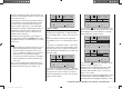
If the carburettor is too far open (or the speed controller
not at “stop”) when you switch the transmitter on, you
will hear an audible warning, and the screen displays
the message:
throttle
too
high !
Tip:
Y
ou can call up the “Servo display” menu to check the
infl uence of the throttle limit slider. This menu can be
accessed from virtually any menu points by simultane-
ously pressing the ef buttons of the left-hand four-way
button. Bear in mind that servo output 6 controls the
throttle servo on the mx-12 HoTT.
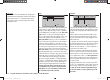
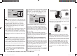
Basic idle setting
Start by turning the throttle limiter - by default the rotary
proportional knob CTRL 7 located at top left on the
transmitter - clockwise to its end-point. Move the throt-
tle / collective pitch stick to the maximum position, and
ensure that a standard throttle curve is active in the
“Channel 1 ¼ throttle” sub-menu of the …
“Heli mixer” (page 94 … 105)
… menu. If you have already altered the standard
throttle curve which is present when you fi rst initialise a
model memory, then this should be reset to the values
“Point 1 = -100%”, “Point 3 = 0%” and “Point 5 = +100%”
- at least temporarily.
33112_mx12_HoTT_2_GB.indd Abs28:7933112_mx12_HoTT_2_GB.indd Abs28:79 06.06.2011 19:39:3906.06.2011 19:39:39