
User's Manual

80
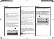
Program description: transmitter control settings – model helicopter
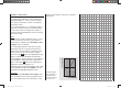
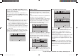
input
output
point 3
0%
0%
0%
ch1 thr
Note:
Since the throttle trim lever has no effect when the throt-
tle limiter is open, its position is not relevant at this point.
Now - without starting the glow motor - adjust the
mechanical linkage of the throttle servo so that the
carburettor barrel is fully open; if necessary, carry out
fi ne-tuning using the travel setting for servo 6 in the
“Servo settings” menu.
Close the throttle limiter completely by turning the rotary
proportional knob CTRL 7 anti-clockwise to its end-
point. Use the trim lever of the throttle / collective pitch
stick to move the trim position marker to the motor OFF
position (see illustration in the right-hand column of the
next page).
Note:
In contrast, when the throttle limiter is closed, the posi-
tion of the throttle / collective pitch stick is not relevant;
it can therefore be left in the maximum collective pitch
position, i. e. the throttle linkage can be adjusted be-
tween full-throttle (throttle limiter open) and “motor OFF”
(throttle limiter closed) using just the throttle limiter.
Now, with the throttle limiter closed, adjust the mechani-
cal throttle linkage so that the carburettor is just fully
closed. However, do check carefully that the throttle
servo is not stalled at either of its extreme end-points
(full-throttle / motor OFF).
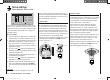
GRAUBELE
#01
3:33h
stop
flt
K78
0:00
0:00
RX0.0V
50%
5.2V
2.4
M
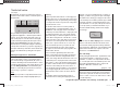
CTRL 7
Current trim position
Trim at motor OFF posi
t
Last idle position
Throttle limit con
t
For this reason the Ch 1 trim display is also completely
suppressed as soon as the throttle limit control is moved
to the right of the centre position.
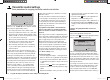
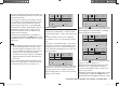
GRAUBELE
#01
3:33h
stop
flt
K78
0:00
0:00
RX0.0V
50%
5.2V
M
2.4
CTRL 7
Throttle limit contro
Note:
Since this trim function is only effective in the “Motor
off” direction, the illustration above changes if you alter
the transmitter control direction for the collective pitch
minimum position of the Ch 1 stick from “back” (refl ected
in the picture above) to “forward” in the “Collective pitch
min.” line of the “Basic settings” menu. In the same
way the effects shown in the illustration swap sides if
you change the stick mode from collective pitch right
(refl ected in the pictures above) to collective pitch left in
the “Stick mode” line of the “Basic settings” menu; see
page 67.
To complete this basic set-up you still have to adjust the
idle trim range to coincide with point “1” of the throttle
curve. This is accomplished by setting point “1” of the
“Ch 1 ¼ throttle” mixer in the “Heli mixer” menu to a
value of about -65 to -70%:
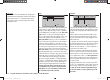
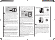
input
output
point 1
–100%
–66%
–66%
ch1 thr
To check that the setting is exact, i. e. that there is a
seamless transition from idle trim to the throttle curve,
you need to close the throttle limiter and move the
collective pitch stick to and fro slightly at the minimum
end-point. When you do this, the throttle servo must not
move! In any case fi ne-tuning must be carried out with
the model fl ying.
The motor is always started with the throttle limiter
completely closed; this has the effect that the idle speed
is adjusted solely using the trim lever of the throttle /
collective pitch stick.
Throttle limit in conjunction with the digital trim
When used with the throttle limit control CTRL 7, the
Ch 1 trim places a marker at the set idle position of the
motor; at this point the motor can be stopped using the
trim. If the trim is in its end-range (see screen-shot: top
picture in the right-hand column), then a single click
immediately takes you back to the marker, i. e. to the
pre-set idle position (see also page 40).
The cut-off trim only acts as idle trim in the left-hand half
of the travel of the throttle limit control, i. e. the marker is
only set and stored within this range.
33112_mx12_HoTT_2_GB.indd Abs28:8033112_mx12_HoTT_2_GB.indd Abs28:80 06.06.2011 19:39:3906.06.2011 19:39:39