
User's Manual

89
Program description: wing mixers – fi xed-wing model
changing fl aps are defi ned; this is intentional, as it
eliminates the danger of errors when a fl ap command
is given. In this case the only type of brake function
available is the Butterfl y or Crow arrangement; see
page 92.
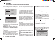
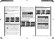
The basic programming procedure
Use the 1. cd buttons of the left or right-hand four-
way button to select the desired mixer.
Use the2. f button of the left or right-hand four-way
button to move to the right-hand column, marked
by the switch symbol
at the bottom edge of the
screen.
Press the central 3. SET button of the right-hand four-
w
ay button; the corresponding input fi eld is now high-
lighted (black background).
Use the arrow buttons of the right-hand four-way but-4.
ton to set the desired value, and assign the switch if
necessary, as described on page 39.
With the exception of the “Diff. red.” line, negative and
positive parameter values are possible; this may be
necessary to obtain the correct direction of servo ro-
tation (control surface defl ection).
Simultaneously pressing the cd or ef buttons of
the right-hand four-way button (CLEAR) resets an al-
tered value to the default value.
Press the central 5. SET button of the right-hand four-
w
ay button to conclude the input process.
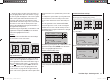
Mixer neutral point (offset)
The neutral point of the mixers …
Aileron ¼ NN *
Elevator ¼ NN *
Elevator ¼ NN *
… is by default the zero point of the transmitter control,
i. e. that is the point at which they have no effect. At the
end-point of the transmitter control the full mixer value is
applied.
The default neutral point (“offset”) of the mixers …
Airbrake ¼ NN *
… at which the airbrakes are always retracted, is the
forward position of the Ch 1 stick (throttle / airbrakes)
if you select “none” in the “Motor at Ch 1” line of the
“Basic settings” menu, and is the back position of the
Ch 1 stick if you select “none/inv”.
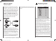
diff aile (differential aileron travel)
Aileron differential compensates for an unwanted side-
effect which occurs when ailerons are defl ected: the
problem known as “adverse yaw”. When ailerons are
defl ected, the drag generated by the down-going aileron
is greater than that produced by the up-going aileron.
The differential drag causes a yawing motion around the
vertical axis in the opposite direction to the desired turn.
This effect is much more pronounced in model gliders
with high aspect ratio wings than in power models with
their much shorter moment arms, and usually has to be
countered by giving a simultaneous rudder defl ection in
the opposite direction to the yaw. However, this in turns
causes additional drag and reduces the aircraft’s ef-
fi ciency even further.
Aileron differential reduces the angular travel of the
down-going aileron relative to the up-going aileron, and
this reduces the drag and therefore the adverse yaw.
However, electronic differential can only be applied
if each aileron is actuated by its own servo, usually
mounted in the wings themselves. The shorter pushrods
also result in virtually slop-free aileron linkages with
Notes:
There are various alternative methods of positioning •
the camber-changing fl aps; these include:
a) settling on just one position per fl ight phase, sim-
ply by setting appropriate trim values in the “Pha-
se trim” menu, as described on the preceding
double-page;
b) controlling the fl aps manually using any transmit-
ter control assigned to “Input 6” (in the “Transmit-
ter control settings” menu - see page 74), after
setting the basic fl ap positions in the “Phase trim”
menu, as described earlier. Ideally the transmit-
ter control would be one of the rotary proportional
controls CTRL 7 or 8.
The selected transmitter control directly operates
the two fl ap servos connected to receiver outputs
6 and 1, assuming that you have specifi ed fl aps in
the “Ail. / Flap” line of the “Basic settings” menu.
The same control determines the fl ap setting of
the ailerons via the percentage value entered in
the “FL ¼ AIL” mixer line.
However, for fi ner control of the fl ap positions, we
recommend that you reduce their travel to about
25% in the “E6” line of the “Transmitter control
settings” menu.
c) It is also possible to leave the default setting of
“0%” in the appropriate line of the “FL ¼ AIL”
menu, and to assign the same transmitter con-
trol to both input 6 and input 5 in the “Transmitter
control settings” menu. The magnitude of the ef-
fect on the two pairs of wing fl aps can then be ad-
justed using the servo travel adjustment facility.
If the Ch 1 stick is assigned to input 1 as standard, •
it will be de-coupled by the software if two camber-
* NN = Nomen Nominandum (name to be stated)
33112_mx12_HoTT_2_GB.indd Abs32:8933112_mx12_HoTT_2_GB.indd Abs32:89 06.06.2011 19:39:4006.06.2011 19:39:40