
User's Manual

90
Program description: wing mixers – fi xed-wing model
Note:
Negative values are not usually necessary if the correct
channels are used.
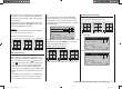
ail ¼ rudd (Aileron ¼ rudder)
In this case the rudder automatically “follows” when an
aileron command is given, and the mixer ratio (degree of
following) can be set by the user. Coupled aileron / rud-
der (also known as “combi-switch”) is especially useful
for suppressing adverse yaw in conjunction with aileron
differential, and this combination usually makes smooth
turns very easy to fl y. Naturally, the rudder can still be
controlled separately by means of its dedicated stick.
The adjustment range of +/- 150% enables the user to
set up the correct direction of travel according to the
direction of rotation of the fl ap servos. If an (optional)
non-centring switch (SW 3 … 7) is assigned to this func-
tion, the mixer can be turned on and off in fl ight, so that
you can control the ailerons and rudder separately if and
when you so desire.
Simultaneously pressing the cd or ef buttons of the
right-hand four-way button (CLEAR) resets an altered
value to 0%.
This mixer is usually set up in such a way that the rud-
der defl ects automatically to the side of the up-going
aileron; a setting around 50% is likely to be approxi-
mately correct.
corresponds to a normal linkage, i. e. no differential,
while “-100%” or “+100%” represents the “split” function.
For aerobatic fl ying it is necessary to set low absolute
differential values, to ensure that the model rotates
exactly along its longitudinal axis when an aileron
command is given. Moderate values around -50% or
+50% are typical for making thermal turns easier to fl y.
The split setting (-100%, +100%) is popular with slope
fl yers, when ailerons alone are often used for turning the
model.
Simultaneously pressing the cd or ef buttons of the
right-hand four-way button (CLEAR) resets an altered
value to 0%.
Note:
Although it is possible to enter negative values in order
to reverse the direction of servo rotation, this is not usu-
ally necessary if the correct channels are used.
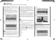
diff fl aps (Camber-changing fl ap differential)
The aileron / fl ap mixer (see below) is designed to
superimpose an aileron function on the fl aps. Flap
differential works like aileron differential, and produces
a reduced fl ap movement in the down-direction when
these surfaces are used as supplementary ailerons.
The adjustment range of -100% to +100% makes it
possible to set the correct direction of differential re-
gardless of the direction of rotation of the servo. “0%”
corresponds to a normal linkage, i. e. the servo travel is
the same up and down. A setting of “-100%” or “+100%”
means that the down-travel of the fl aps is reduced to
zero when an aileron command is given (“split” setting).
Simultaneously pressing the cd or ef buttons of the
right-hand four-way button (CLEAR) resets an altered
value to 0%.
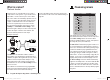
reliable centring.
Mechanical solutions are also possible, but they usually
have to be “designed in” when the model is built, and the
degree of differential cannot be altered subsequently.
In any case signifi cant mechanical differential tends to
cause additional slop in the control system. Electronic
differential offers several important advantages:
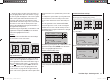
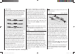
0% (normal)
50% (differential)
100% (split)
It is easily possible to vary the degree of differential
without affecting the travel of the up-going aileron. At
one extreme it is possible to suppress the down-aileron
defl ection completely, i. e. only the up-going aileron
moves at all, and this arrangement is sometimes called
the “split” setting. Split ailerons not only tend to suppress
adverse yaw, but can even generate positive yaw, which
means that the model yaws in the direction of the turn
when an aileron command is given. In the case of large
model gliders, smooth turns can then be fl own using
ailerons alone, which with most models of this type is
usually by no means the case.
The adjustment range of -100% to +100% makes it pos-
sible to set the correct direction of differential regardless
of the direction of rotation of the aileron servos. “0%”
33112_mx12_HoTT_2_GB.indd Abs32:9033112_mx12_HoTT_2_GB.indd Abs32:90 06.06.2011 19:39:4006.06.2011 19:39:40