
User's Manual


92
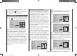
Program description: wing mixers – fi xed-wing model
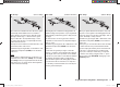
elev ¼ fl ap (Elevator ¼ fl ap)
The fl aps can be used to enhance the effect of the el-
evator in tight turns and aerobatics, and this mixer feeds
part of the elevator signal to the fl ap servos. The mixer
direction must be set so that the fl aps move down when
up-elevator is applied, and vice versa.
Simultaneously pressing the cd or ef buttons of the
right-hand four-way button (CLEAR) resets an altered
value to 0%.
The “usual” settings for this mixer are in the low two-digit
range.
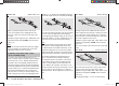
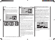
elev ¼ aile (Elevator ¼ aileron)
This mixer allows the ailerons to reinforce the elevator
response in the same way as the previous mixer.
Simultaneously pressing the cd or ef buttons of the
right-hand four-way button (CLEAR) resets an altered
value to 0%.
The adjustment range is +/- 150%. For this mixer the
started too soon, and has to be extended by retracting
the airbrakes again, the model could then stall abruptly.
This inter-action between the fl aps, ailerons and elevator
is used to control the glide angle on the landing ap-
proach. Optionally the butterfl y setting can also be used
without the airbrakes or spoilers; nowadays this is very
commonly used for sports and competition aircraft.
Note:
If your model features full-span (strip) ailerons which
also double as camber-changing fl aps, the two mix-
ers “Brake ¼ aileron” and “Brake ¼ elevator” can be
combined for glide path control. In this case up-fl ap is
applied, but the fl aps can still be controlled as ailerons.
Elevator pitch trim compensation is generally required.
If you have programmed aileron differential, the re-
sponse of the ailerons will inevitably be adversely
affected by the extreme “up” defl ection of the ailerons
in the butterfl y setting, because the differential travel
reduces or entirely suppresses the down-aileron de-
fl ection. However, the “up” travel of the ailerons is also
greatly restricted because they are already at or close to
their “up” end-point. The remedy here is to apply “dif-
ferential reduction”, which is explained in its own section
later.
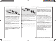
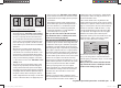
brak ¼ aile (Airbrake ¼ aileron)
When you operate the brake function, both aileron
servos move together for the landing approach; the
mixer ratio can be set to any value in the range -150%
to +150%.
Simultaneously pressing the cd or ef buttons of the
right-hand four-way button (CLEAR) resets an altered
value to 0%.
Note:
It can also be useful to defl ect both ailerons up slightly
when the airbrakes are extended; in most cases this
signifi cantly reduces the risk of a tip-stall.
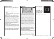
Combination of the “Brake ¼ NN *” mixers:
“Crow” or “Butterfl y” setting
If you have set up all three airbrake mixers for your
model, it is then possible to program a special confi gura-
tion known as the “crow” or “butterfl y” arrangement for
glide path control. In the butterfl y setting both ailerons
are defl ected up by a moderate amount, and both fl aps
down by the maximum possible amount. The third mixer
provides elevator trim to counteract any unwanted pitch
trim change and maintain the model’s airspeed at a
safe level. This is necessary to avoid the danger of the
model slowing up excessively; if the landing approach is
* NN = Nomen Nominandum (name to be stated)
33112_mx12_HoTT_2_GB.indd Abs32:9233112_mx12_HoTT_2_GB.indd Abs32:92 06.06.2011 19:39:4006.06.2011 19:39:40