
User's Manual


94
Program description: helicopter mixers – model helicopter
Helicopter mixers
Flight phase-specifi c mixers for collective pitch, throttle and tail rotor
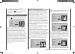
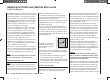
In the “Basic settings” menu a method of switching
fl ight phases can be activated by assigning the appropri-
ate switches to “Phase 2” and / or “Auto-rotation”. You
can then switch between the phases “normal” and a
second phase - to which you can assign a more ap-
propriate name yourself, if necessary - using one of the
non-centring switches SW 3 … 7; a further switch then
selects “Auto-rotation”. However, auto-rotation always
has precedence over the other two phases; see
pages 68 / 69.
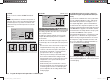
If you have not yet assigned switches for the fl ight
phases, you should do so now. Use the arrow buttons of
the left-hand four-way button to move to the right-hand
column, marked by the switch
symbol at the bottom
of the screen, then press the central SET button of the
right-hand four-way button. The switches are assigned
as described on page 39:
pitch min
rear
timer 10:01 C3
phase 2 hover
autorotat.
5
4
rotor direct right
Phase 1 always bears the designation “normal”. Both
the n
umber and name of this phase are permanently
assigned, and cannot be altered. For this reason the
“normal” phase is not stated as Phase 1 in the “Basic
settings” menu; it is simply concealed.
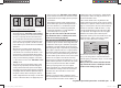
By default “Phase 2” is assigned the phase name “hov-
er”, but you can change these at any time if you prefer:
press the central SET button with the right-hand four-
w
ay button, and use the arrow buttons of the right-hand
four-way button to select one of the following names:
hover•
acro•
acro 3D•
speed•
test•
Description of the helicopter mixers
Five-point curves are available for setting up the control
characteristics of “collective pitch”, “Ch 1 ¼ throttle” and
“Ch 1 ¼ tail rotor”. Using these curves it is possible to
program non-linear mixer ratios along the travel of the
transmitter stick for these mixers. Move to the display
page for setting 5-point curves by pressing the central
SET button of the right-hand four-way button (see
belo
w).
In contrast, the mixers “Ch 1 ¼ throttle” and “Ch 1 ¼
tail rotor” are not required for the “Auto-rotation” fl ight
phase (described in the section starting on page 104);
instead they are automatically switched to a (user-varia-
ble) pre-defi ned value.
A value must be entered in the “Gyro” line: press the
central SET button of the right-hand four-way button,
then enter a v
alue in the highlighted fi eld using the arrow
buttons of the right-hand four-way button - in a similar
fashion to changing the transmitter centre position or
the offset position with other radio control systems. This
set-up facility is rounded off with the “Swashplate limit”
option: this restricts the maximum travel of the swash-
plate servos to the value you set, in the form of a limiter.
All these options are required for the basic process of
setting up a model helicopter.
Altered parameters can be reset to the corresponding
default values at any time by simultaneously pressing
the cd or ef buttons of the right-hand four-way
button (CLEAR).
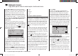
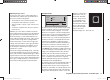
The name of the currently selected fl ight phase is
displayed in the “Helicopter mixers” menu as well as
in the transmitter’s basic display; this is designed to
ensure that any changes you make actually apply to
the appropriate fl ight phase. Note that the servos do not
change from one setting to another abruptly; they move
smoothly with a transition time of around one second.
This does not apply to auto-rotation: when you switch
INTO auto-rotation, the change takes place immediately.
If you operate the switch selected for a particular fl ight
phase, the associated fl ight phase is superimposed at
the left-hand bottom edge of the screen, e. g. “normal”.
ch1
ch1
ptch
thro
tail
normal
gyro
0%
SEL
swash lim. off
Now you can program the settings for this fl ight phase.
Basic programming procedure
Use the arrow buttons 1. cd of the left or right-hand
four-way button to select the desired option.
Press the central 2. SET button of the right-hand four-
w
ay button, and the screen switches to the set-up
page ( symbol at the bottom edge of the screen),
or the corresponding input fi eld is highlighted (black
background).
Defi ne the mixer values using the arrow buttons of 3.
the right-hand four-way button, moving the throttle /
collective pitch stick at the same time if necessary.
Simultaneously pressing the 4. cd or ef buttons of
33112_mx12_HoTT_2_GB.indd Abs33:9433112_mx12_HoTT_2_GB.indd Abs33:94 06.06.2011 19:39:4106.06.2011 19:39:41