
User's Manual


96
Program description: helicopter mixers – model helicopter
(CLEAR).
Points “1” and “5”, however, CANNOT be disabled.
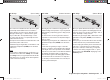
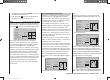
Note:
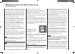
The following illustration, and all the other pictures on
this page, show a control curve which we prepared for
illustration purposes only. Please note that the curve
characteristics by no means represent real collective
pitch curves!
input
output
point 3
0%
–50%
–50%
ptch
normal
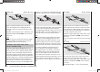
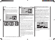
Typical collective pitch curves for different fl ight phases:
+100% +100% +100%
-100%
-100%
-100%
Output
Output
Output
23451
23451
23451
Control travel Control travel Control travel
Hover
Aerobatics 3D
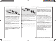
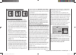
ch1 ¼ thro (throttle curve)
input
output
point
3
0%
0%
0%
ch1
normal
thro
Helicopter with glow engine or electric motor and
ST
ANDARD SPEED CONTROLLER
This setting only affects the control curve of the throttle
servo or speed controller.
The method of setting up a throttle curve for a model
helicopter fi tted with a speed governor or regulator is
discussed later.
The throttle curve can be defi ned using up to fi ve points,
in a similar way to the collective pitch curve (see previous
page).
In all cases the control curve must be set up in such •
a way that the throttle is fully open, or the speed
controller of an electric helicopter is at full power, at
the end-point of the throttle / collective pitch stick,
(exception: auto-rotation - see page 104).
The hover point is normally located at the centre of •
the stick travel, and the throttle setting should be
adjusted relative to the collective pitch curve in such
a way that the correct system rotational speed is
obtained at this point.
At the minimum position of the throttle / collective •
pitch stick the throttle curve should initially be set up
so that the (glow) motor runs at a distinctly higher
speed compared to the idle setting, with the clutch
reliably engaged.
In all fl ight phases the motor (glow or electric) is
started and stopped using the throttle limiter (see
below).
If you are used to a different radio control system which
uses two separate fl ight phases for this - “with idle-up”
and “without idle-up”; therefore incurring the “loss” of
one complete fl ight phase - please note that the throt-
tle limiter renders this complication superfl uous, as the
increased system rotational speed below the hover point
in the mx-12 HoTT program is more fl exible, and can
be fi ne-tuned more accurately, than the “idle-up” system
used with earlier mc radio control systems.
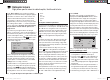
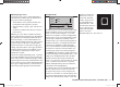
Ensure that the throttle limiter is closed before you start
the glow motor, i. e. the throttle can only be adjusted
within its idle range using the idle trim. Be sure to read
the safety notes on page 102 which refer to this. If the
idle is set too high when you switch the transmitter on,
you will see and hear a clear warning!
stop
STARLET
#02
2:22h
Flug
K78
0:00
0:00
5.5V
5.2V
HoTT
99%
«normal »
M
throttle
too
high !
The following three diagrams show typical 3-point throttle
cur
ves for different fl ight phases, such as hover, aerobat-
ics and 3-D fl ying.
33112_mx12_HoTT_2_GB.indd Abs33:9633112_mx12_HoTT_2_GB.indd Abs33:96 06.06.2011 19:39:4106.06.2011 19:39:41