
User's Manual


98
Program description: helicopter mixers – model helicopter
tems.
We recommend that you set up switchable fl ight phases
for this, and set different gain settings for each phase in
the “Gyro” line; values between -125% and +125% are
possible.
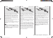
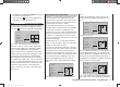
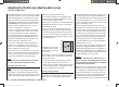
ch1
ch1
ptch
thro
tail
normal
gyro
0%
SEL
swash lim. off
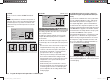
Based on the offset values determined for each fl ight
phase
, gyro gain can be varied proportionally by means
of a transmitter control assigned in the “Gyro” line of the
“Transmitter control settings” menu (see page 78).
This could be CTRL 8, which would provide infi nitely
variable gyro gain control:
At the centre position of this transmitter control •
the gyro effect always corresponds to the settings
selected here.
If you turn the rotary proportional control CTRL 8, •
which we are using in our example, in the direction of
full travel (away from centre), the gyro gain increases
accordingly …
… and diminishes again if you turn it in the direction •
of the opposite end-point.
Important Note:
It is absolutely essential to read and observe the
set-up instructions supplied with your gyro before
entering any settings at this point, as a mistake here
could render your helicopter uncontrollable.
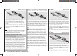
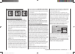
Ch1 ¼ tail rotor (static torque compensation)
input
output
point
3
0%
0%
0%
Ch1
normal
tail
The default setting is a torque compensation curve with a
unif
orm linear mixer input of 0%, as is required for a gyro
sensor operating in “heading lock mode”; see illustration
above.
Important Note:
It is absolutely essential to read and observe the
set-up instructions supplied with your gyro before
entering any settings at this point, as a mistake here
could render your helicopter uncontrollable.
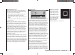
If you use your gyro sensor in “normal” operating mode,
or if the gyro only offers “normal mode”, then you should
set up the mixer as follows:
The tail rotor control curve can be defi ned using up to
fi ve points, in a similar way to the collective pitch curve
(see previous page). You can therefore modify the mixer
at any time when required, and enter symmetrical or
asymmetrical mixer inputs both above and below the
hover point. However, please ensure at the outset that
you have entered the correct direction of main rotor rota-
tion in the “Basic settings” menu.
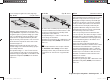
input
output
point
3
0%
0%
0%
CH1
normal
tail
Starting from -30% at Point 1 and +30% at Point 5, this
mix
er should be set up in such a way that the helicopter
does not rotate around the vertical (yaw) axis (i. e. does
not deviate from the hover heading) during a long vertical
climb or descent, due to the change in torque of the main
rotor. At the hover the yaw trim should be set using the
(digital) tail rotor trim lever only.
For a reliable torque compensation setting it is essential
that the collective pitch and throttle curves have been set
up correctly, i. e. that main rotor speed remains constant
over the full range of collective pitch.
When you select auto-rotation, this mixer is auto-
matically switched off.
Gyro (adjusting gyro gain)
Most modern gyro systems feature proportional, infi nite-
ly variable adjustment of gyro gain as well as a means
of selecting either of two different methods of working
from the transmitter.
If the gyro you wish to use features at least one of these
options, then it offers you the possibility of pre-setting
both “normal” gyro effect and - if available - “heading
lock mode”, and also of fl ying normal, slow circuits with
maximum gyro stabilisation, but reducing the gyro effect
for high-speed circuits and aerobatics. This is generally
similar to the transmitter control centre adjustment or
offset adjustment provided by other radio control sys-
33112_mx12_HoTT_2_GB.indd Abs33:9833112_mx12_HoTT_2_GB.indd Abs33:98 06.06.2011 19:39:4106.06.2011 19:39:41