
User's Manual


99
Program description: helicopter mixers – model helicopter
Adjusting the gyro sensor
If y
ou wish to set up a gyro to achieve maximum pos-
sible stabilisation of the helicopter around the vertical
axis, please note the following points:
The mechanical control system should be as free-•
moving and accurate (slop-free) as possible.
There should be no “spring” or “give” in the tail rotor •
linkage.
You must use a powerful and - above all - fast servo •
for the tail rotor.
When the gyro sensor detects a deviation in yaw, the
faster it adjusts the thrust of the tail rotor, the further the
gyro gain adjuster can be advanced without the tail of
the model starting to oscillate, and the better the ma-
chine’s stability around the vertical axis. If the corrective
system is not fast enough, there is a danger that the
model’s tail will start to oscillate even at low gyro gain
settings, and you then have to reduce gyro gain further
using the rotary proportional control CTRL 8, as used
in our example, to adjust the pre-set “Gyro” value to
eliminate the oscillation.
If the model is fl ying forward at high speed, or hovering
in a powerful headwind, the net result of the stabilising
effect of the vertical fi n combined with the gyro’s stabilis-
ing effect may be an over-reaction which manifests itself
as tail oscillation. In order to obtain optimum stabilisation
from a gyro in all fl ight situations, you should make use
of the facility to adjust gyro gain from the transmitter.
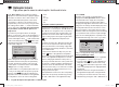
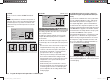
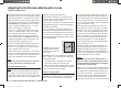
Swashplate limiter
ch1
ch1
ptch
thro
tail
normal
gyro
0%
SEL
swash lim. off
This function acts like a circular mechanical gate acting
upon the s
washplate control stick, restricting its range
of travel - which is usually rectangular - to a circular
pattern. This is designed to solve the following problem:
if the helicopter is set up in such a way that the roll and
pitch-axis travels extend to the maximum possible in
mechanical terms, e. g. for 3-D helicopter fl ying, then at
simultaneous full travel of roll and pitch-axis the actual
movement of the swashplate is higher (theoretically
141%). In this situation the mechanical swashplate sys-
tem may strike its end-stops, and in the extreme case
the ball-links may even be forced off the linkage balls.
In the mx-12 HoTT transmitter a software function has
the effect of limiting the overall swashplate travel, i. e. the
tilt angle of the swashplate between 100% (the travel
is limited to the value which can be reached by one
function - roll or pitch-axis - alone) and 149% (no limiting
in force) is switched “off” (the function is completely
disabled). Swashplate limiting can also be adjusted to
suit individual models and fl ight phases.
This software solution is far more fl exible than a physical
limiter disc attached to the stick unit, and such a disc
can only be used in any case if the roll and pitch-axis
functions are controlled by one of the two primary sticks.
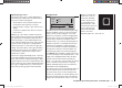
The sketch alongside shows the effect of the limiter at a
setting of 100%: the dotted area of travel is cut off, and
appears as a dead zone. If
this function is used, you
should leave “Dual Rate”
at 100%, and you should
not set Dual Rate values
greater than 100%, other-
wise travel will be limited on
the roll or pitch-axis indi-
vidually if the swashplate
limiter is set to 100%.
Adjustment range: 100 ... 149% and “off”.
33112_mx12_HoTT_2_GB.indd Abs33:9933112_mx12_HoTT_2_GB.indd Abs33:99 06.06.2011 19:39:4106.06.2011 19:39:41