
User's Manual
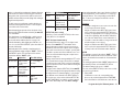

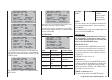
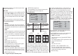
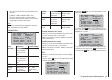

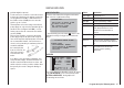

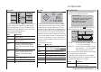
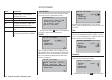
Table Of Contents
- Programming Manual 33116.mx-16 HoTT.1.gb
- Contents
- Safety Notes
- Safety notes and handling instructions relating to Nickel-Metal-Hydride rechargeable batteries
- Introduction
- Operating Notes
- Description of transmitter
- Using for the first time ...
- Installation Notes
- Definition of terms
- Assigning switches and control switches
- Digital trims
- “Binding” transmitter and receiver
- What is a mixer?
- General notes regarding freely programmable mixers
- Fixed-wing model aircraft
- Receiver socket assignment for "normal" models
- Receiver socket assignment for models of the “Delta / Flying wing” type
- “Binding” transmitter and receiver
- Detailed description of programming
- mx-16 HoTT programming techniques
- Model helicopters
- Receiver socket assignment
- “Binding” transmitter and receiver
- Detailed description of programming
- Programming example
- Appendix
- Guarantee certifi cate

126
Program description: Telemetry menu
ALARM VOLT (low receiver voltage warning)
ALARM VOLT monitors the receiver voltage. The thresh-
old can be set to any value within the range 3.0 to 6.0
Volt. If the voltage falls below the set alarm limit, an
audible signal (interval beeping, long / short) is trig-
gered, and “VOLT.E” fl ashes at top right in all “RX …”
screen displays:
RX SERVO
REVERSE : OFF
CENTER : 1500μsec
TRIM : –000μsec
TRAVEL– : 150%
OUTPUT CH: 01
TRAVEL+ : 150%
PERIOD : 20msec
VOLT.E
The parameter R-VOLT is also highlighted in the “RX
DATAVIEW” display:
RX DATAVIEW
S–STR100% R–TEM.+28°C
L PACK TIME 00010msec
L.R-VOLT:04.5V
S–QUA100%S–dBM–030dBM
SENSOR1 :00.0V 00°C
SENSOR2 :00.0V 00°C
R-VOLT :05.0V
ALARM TEMP +/- (receiver temperature monitor)
These two options monitor the temperature of the
receiver: a lower limit value “ALARM TEMP-” (-20 ...
+10°C) and an upper limit value “ALARM TEMP+” (50 ...
80°C) can be programmed. If the temperature exceeds
the upper limit or falls below the lower one, an audible
signal (continuous beeping) is triggered, and “TEMP.E”
appears at top right in all receiv
er displays. The param-
eter R-TEM is also highlighted in the “RX DATAVIEW”
display.
Ensure that the receiver remains within the permitted
temperature range under all fl ight conditions (ideally
between -10 and +50°C).
CH OUTPUT TYPE
At this point you can select how the receiver outputs are
to be addressed.
ONCE•
The receiver servo sockets are addressed in se-
quence; this is recommended for use with analogue
servos. At this setting the servos are automatical-
ly operated at a frame rate of 20 ms (30 ms with the
twelve-channel receiver, Order No. 33512) - regard-
less of what is set or displayed in the “PERIOD” line
of the “RX SERVO” display.
SAME•
The receiver servo sockets are addressed in parallel
blocks of four, i. e. channels 1 to 4 and channels 5 to
8 each receive their control signals simultaneously.
This is recommended for use with digital servos, and
especially where multiple servos are employed for
a single function (e. g. ailerons), to ensure that the
groups of servos run absolutely synchronously.
If you are using digital servos, we recommend that
you set 10 ms in the “PERIOD” line of the “RX SER-
VO” display so that you can exploit the fast response
of these servos. If you are using analogue servos, it
is essential to select “20 ms”.
If you choose the faster setting, please take par-
ticular care when selecting the receiver power
supply: since up to four servos can start moving si-
multaneously, the load on the battery is fairly severe,
so it must be a high-performance type.
SUMI / SUMO (sum signal IN / OUT)•
The HoTT transmission system allows a single trans-
mitter to control more than one receiver: either in
“Master - Slave” arrangement, or in “Satellite mode”,
as described here.
In …
Satellite mode
… two HoTT receivers are inter-connected using a
three-core connecting lead (Order No. 33700.1 (300
mm) or 33700.2 (100 mm) by the highest-numbered
servo sockets. For more details on this please visit
www.graupner.de on the Internet.
The HoTT receiver which is confi gured as SUMO
(see below) is designated the satellite receiver, and
all its channels are transmitted in the form of a sum
signal to the second HoTT receiver - the primary re-
ceiver - if reception should fail; the primary receiver
must be programmed as “SUMI”. Note that the signal
only ever moves towards SUMI.
The receiver outputs are addressed in sequence at a
frame rate of 20 ms (30 ms with the GR-24 receiver,
Order No. 33512), even if you have set 10 ms in the
“PERIOD” line of the “RX SERVO” screen page.
However, if the receiver programmed as the satellite
(SUMO) suffers signal reception failure, the servos
connected to that receiver take up the Fail-Safe posi-
tions programmed in the satellite receiver, regardless
of the primary receiver.
This receiver confi guration is recommended in partic-
ular circumstances: for example, if one of the two re-
ceivers has to be installed in an unfavourable position
in the model, or if there is a danger that the received
signal will be weak in certain fl ight attitudes, per-
haps due to a turbine, carbon fi bre in the airframe, or
a similar problem, with the result that sporadic range