
User's Manual
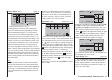
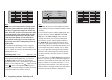

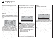
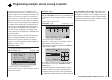

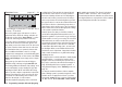


Table Of Contents
- Programming Manual 33116.mx-16 HoTT.1.gb
- Contents
- Safety Notes
- Safety notes and handling instructions relating to Nickel-Metal-Hydride rechargeable batteries
- Introduction
- Operating Notes
- Description of transmitter
- Using for the first time ...
- Installation Notes
- Definition of terms
- Assigning switches and control switches
- Digital trims
- “Binding” transmitter and receiver
- What is a mixer?
- General notes regarding freely programmable mixers
- Fixed-wing model aircraft
- Receiver socket assignment for "normal" models
- Receiver socket assignment for models of the “Delta / Flying wing” type
- “Binding” transmitter and receiver
- Detailed description of programming
- mx-16 HoTT programming techniques
- Model helicopters
- Receiver socket assignment
- “Binding” transmitter and receiver
- Detailed description of programming
- Programming example
- Appendix
- Guarantee certifi cate

152
Programming example - fi xed-wing model
+33%
–5%
+55%
–––
–––
–––
2
–––0%
+44%
ail
diff aile.
rudd
brak
brak
elev
aile
elev aile
Note:
The settings shown here are just examples
, and must
not be adopted under any circumstances without careful
checking.
If your model also features camber-changing fl aps, and
you have therefore selected “2AIL 2FL” in the “Aile
/ fl ap” line of the “Basic settings” menu, locate the
“change-over switch” you have just operated (in this
case switch 2), move it “forward” again and switch to
the “Brake ¼ FL” line using the arrow buttons cd
of the left or right-hand touch-key. You can now set the
desired down-defl ection of the fl aps when the Ch 1 stick
is moved (this fl ap position is termed “crow” or “butter-
fl y”; see also page 92), and assign the external switch
which also acts as the change-over switch by moving
it from the “forward” to the “back” position, as already
described.
If you now return to the “Servo display” menu and move
the Ch 1 stick alone, you will see that the bar display for
Channel 1 either remains at around -100% while the dis-
plays for channels 2 + 5 (and also the fl aps 6 + 7, if set
up) follow the stick movement, or the other way round:
when the switch is operated, the latter stay at around the
mid-point, and only the Channel 1 display moves.
1
3
5
7
2
4
6
8
0%
0%
0%
–100%
0%
–88%
0%
+88%
1
3
5
7
2
4
6
8
0%
0%
0%
0%
–100%
0%
0%
0%
Note:
If you carry out this test with the receiving system
and po
wer system switched on, please take great
care that you operate the change-over switch only
in the “motor OFF” position! If you ignore this, there
is a danger that the power system will be severely
overloaded by being switched on abruptly, and it
could even suffer damage. For the same reason
you should be careful only to use the change-over
switch at the “motor OFF” setting when you are fl y-
ing the model.
To conclude the programming procedure, return the
selected “change-over switch” to the “motor ON” posi-
tion, i. e. “forward”; move back to the multi-function menu
and from there to the …
“Fixed-wing mixers” menu (pages 88 … 93)
where - assuming that you have not already done this
in your general model programming - you can select
the “Brake ¼ AIL” line and set the desired aileron
travel when the Ch 1 stick is operated in the up direction
(“Brake”). In the column above the
symbol touch the
central SET button of the right-hand touch-key before
assigning your selected “change-over switch” by moving
your preferred switch from “forward” to “back”.