
User's Manual
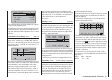

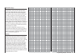
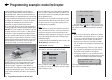

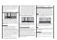
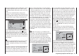
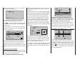
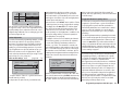

Table Of Contents
- Programming Manual 33116.mx-16 HoTT.1.gb
- Contents
- Safety Notes
- Safety notes and handling instructions relating to Nickel-Metal-Hydride rechargeable batteries
- Introduction
- Operating Notes
- Description of transmitter
- Using for the first time ...
- Installation Notes
- Definition of terms
- Assigning switches and control switches
- Digital trims
- “Binding” transmitter and receiver
- What is a mixer?
- General notes regarding freely programmable mixers
- Fixed-wing model aircraft
- Receiver socket assignment for "normal" models
- Receiver socket assignment for models of the “Delta / Flying wing” type
- “Binding” transmitter and receiver
- Detailed description of programming
- mx-16 HoTT programming techniques
- Model helicopters
- Receiver socket assignment
- “Binding” transmitter and receiver
- Detailed description of programming
- Programming example
- Appendix
- Guarantee certifi cate

166
Programming example: model helicopter
throttle servo. This section does not describe the spe-
cial features of this trim (“cut-off trim”) again, as it
is covered on page 40. (Thanks to the digital trims,
trim values are automatically stored when you switch
models and when you switch between fl ight phases.)
You will fi nd a detailed description of the basic idle •
set-up procedure and the method of adjusting idle
and throttle limit in the section starting on page 79.
Now use the arrow button f of the left or right-hand
touch-key to move to the “Travel” column, and increase
the value in the highlighted fi eld from 100% to 125%,
with the throttle limiter at its forward end-stop.
+
+100%
+100%
+100%
+100%
+100%
+100%
+100%
+100%
+100%
+125%
trv
free
free
ctrl6
E5
Gas
Gyr
E8
Lim
free
free
This ensures that the throttle limiter cannot possibly
restrict the full throttle tr
avel dictated by the collective
pitch stick when the model is in fl ight.
Set-up note for electric helicopters:
Since electric motors by their nature require no idle
setting, the only important point when setting up an
electric-powered model helicopter is that the adjustment
range of the throttle limiter should be set signifi cantly
higher and lower than the adjustment range of the
speed controller, which is usually from -100% to +100%.
It may therefore be necessary to adjust the “Travel” value
of the throttle limiter to an appropriate value, such as a
symmetrical 110% setting. However, further fi ne-tuning
can be carried out exactly as described here for the
glow-powered machine.
tion of rotation of any servo; do check carefully that the
direction you set really is correct. The tail rotor servo,
in particular, must operate in such a way that the nose
(!) of the helicopter moves in the direction which corre-
sponds to the movement of the tail rotor stick.
A glance at the …
“Transmitter control settings” menu (page 76)
+
trv
free
free
ctrl6
E5
Gas
Gyr
E8
Lim
+100%
+100%
+100%
+100%
+100%
+100%
+100%
+100%
+100%
+100%
free
free
… will show you that transmitter control “6”, i. e. the
rotary propor
tional control CTRL 6, is assigned to the
“Lim” input, whereas all other inputs are programmed
to “free” by default. The “Lim” input serves as throttle
limiter. It acts solely on output “6”, to which the throttle
servo is connected.
Just to remind you:
Using the “Throttle limiter” function eliminates the •
need to program an “Idle-up” fl ight phase.
The throttle limiter does not control the throttle ser-•
vo; it simply limits the travel of this servo in the for-
ward direction, according to the setting of the throt-
tle limiter, when required. The throttle servo is usually
controlled by the collective pitch stick via the throttle
curve or curves you have set in the “Helimix” menu,
for which reason input 6 should always be left “free”.
For more details please refer to the sections on pag-
es 96 and 97 of the manual.
Moreover the Ch 1 trim only affects a helicopter’s •
An additional function needs to be activated in the …
“Basic model settings” menu (pages 64 … 71).
Even if you are a beginner to fl ying and are not yet
ready for this, it is advisable at least to defi ne the auto-
rotation switch, so that you have an “emergency cut”
switch for the motor. This is carried out by selecting the
“Auto-rotation” line using the arrow buttons cd of the
left or right-hand touch-key, briefl y touching the central
SET button of the right-hand touch-key, and then moving
one of the two-position s
witches (SW 2 or 8) to the “ON”
setting. The switch number (in our example “2”) now
appears on the right of the screen.
rear
5:00
C3
2
–––
–––
phase 2
phase 3
hover
speed
pitch min
timer
autorotat.
This switch should be located at a position on the trans-
mitter where you can easily reach it without letting go of
the stic
k, e. g. above the collective pitch stick.
Note:
For more information on setting up this “emergency OFF
switch” please refer to the section in the centre column
of the following page.
And another tip:
Please make it a habit to give all the switches a common
“on” direction; then a quick glance at the transmitter
before fl ying will soon reassure you that all switches are
“off”.
If you wish, you could at this point move up two lines