
User's Manual
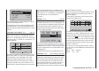

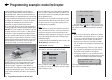

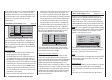
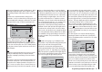
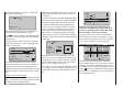
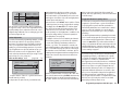

Table Of Contents
- Programming Manual 33116.mx-16 HoTT.1.gb
- Contents
- Safety Notes
- Safety notes and handling instructions relating to Nickel-Metal-Hydride rechargeable batteries
- Introduction
- Operating Notes
- Description of transmitter
- Using for the first time ...
- Installation Notes
- Definition of terms
- Assigning switches and control switches
- Digital trims
- “Binding” transmitter and receiver
- What is a mixer?
- General notes regarding freely programmable mixers
- Fixed-wing model aircraft
- Receiver socket assignment for "normal" models
- Receiver socket assignment for models of the “Delta / Flying wing” type
- “Binding” transmitter and receiver
- Detailed description of programming
- mx-16 HoTT programming techniques
- Model helicopters
- Receiver socket assignment
- “Binding” transmitter and receiver
- Detailed description of programming
- Programming example
- Appendix
- Guarantee certifi cate

168
Programming example: model helicopter
auto-rotation fl ight phase, you will see - instead of the
usual display - the following:
c1
Autorot
thro
off
This means that the throttle servo has switched to a
fi x
ed value, which can be adjusted as follows:
Press ESC to return to the menu list. Assuming that you
are still in the auto-rotation phase, this will now include
ne
w sub-menus.
The important line is “Throttle”, where you should set
a value of around +125% or -125%, depending on the
direction of servo rotation.
tail
ptch
thro
Autorot
gyro
0%
inp8 0%
0%
–125%
This setting ensures that the motor stops reliably in
the auto-rotation phase (to allow you to cope with an
emergency). Later, when you have gained suffi cient
experience to practise auto-rotation landings, the setting
should be changed to a value which provides a reliable
idle.
Set-up note for electric helicopters:
Since the motor must be stopped completely if an emer-
gency occurs with an electric-powered model helicopter,
this setting can be adopted unchanged.
At present the remaining sub-menus are of no interest.
Simply switch “Auto-rotation” off, and move back to the
fi rst menu list.
Call up the set-up page of the “Ch1 ¼ tail rotor” menu:
this is where you set static torque compensation (DMA)
for the tail rotor. Once again, please restrict yourself
to the three default reference points; everything else
is the preserve of the experienced pilot. For the initial
set-up - intended for a heading-lock gyro system - the
uniform pre-set values of 0% should be changed to
-30% at Point 1 (collective pitch minimum) and +30%
at the opposite end, Point 5 (collective pitch maximum),
although you may fi nd it necessary to adjust the settings
slightly later.
input
output
point
5
–100%
–30%
–30%
c1
normal
tail
Now switch back to the auto-rotation phase for a mo-
ment.
The set-up cur
ve is disabled here, with the result
that the tail rotor servo no longer responds to collective
pitch commands (when the main rotor is not powered,
there is no rotor torque to be corrected).
The - static - pre-set of the gyro effect principle (“normal”
or “heading lock” mode), and also the gyro gain can now
be altered by setting a value other than “0” in the “Gyro”
line:
ch1
ch1
ptch
thro
tail
normal
gyro
0%
inp8 0%
Please be sure to read and observe the set-up
instructions supplied with your gyro at this point,
as there is a possibility that your helicopter will be
uncontrollable if you set it up incorrectly!
If your gyro features gain control from the transmitter -
unlike the type we are using in this example - you will
need another free proportional control for it, e. g. CTRL
7. This can be assigned to the “Gyro” input in the …
“Transmitter control settings” menu (page 76).
+
trv
free
free
ctrl 6
ctrl 7
I5
thr
gyr
I8
lim
+100%
+100%
+100%
+100%
+100%
+100%
+100%
+100%
+100%
+100%
free
Turn the rotary control until its number (transmitter
control number) appears on the screen, then use the ar-
row b
utton f of the left or right-hand touch-key to move
to the ASY fi eld in the “Travel” column. Briefl y press the
central SET button of the right-hand touch-key, and you
will be able to set a maximum gyro gain such as 50% in
the now highlighted fi eld: