
User's Manual


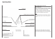
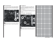

Table Of Contents
- Programming Manual 33116.mx-16 HoTT.1.gb
- Contents
- Safety Notes
- Safety notes and handling instructions relating to Nickel-Metal-Hydride rechargeable batteries
- Introduction
- Operating Notes
- Description of transmitter
- Using for the first time ...
- Installation Notes
- Definition of terms
- Assigning switches and control switches
- Digital trims
- “Binding” transmitter and receiver
- What is a mixer?
- General notes regarding freely programmable mixers
- Fixed-wing model aircraft
- Receiver socket assignment for "normal" models
- Receiver socket assignment for models of the “Delta / Flying wing” type
- “Binding” transmitter and receiver
- Detailed description of programming
- mx-16 HoTT programming techniques
- Model helicopters
- Receiver socket assignment
- “Binding” transmitter and receiver
- Detailed description of programming
- Programming example
- Appendix
- Guarantee certifi cate

20
Description of transmitter
Description of transmitter
Transmitter controls
Aerial with folding / rotating base
Rotary proportional control CTRL 7
3-position switch SW 4/5
2-position momentary
switch SW 1
Rotary proportional
control CTRL 6
Left-hand stick
Tr im
ON / OFF switch
Left-hand touch-button
LCD screen
Right-hand touch-button
Tr im
Right-hand stick
2-position switch SW 3
Carry handle
Neckstrap lug
Attaching the transmitter neckstrap
You will fi nd a strap lug mounted in the centre of the
front face of the mx-16 HoTT transmitter, as shown in
the drawing on the right. This lug is positioned in such a
way that the transmitter is perfectly balanced even when
suspended from a neckstrap.
Order No. 1121 Neckstrap, 20 mm wide
Order No. 70 Neckstrap, 30 mm wide
3-possition switch SW 6/7
Rotary proportional control CTRL 8
Important note:
In the transmitter’s standard form any servos connected
to the receiver can initially only be operated using the
dual-axis sticks. For maximum fl exibility, all the other
transmitter controls (CTRL 6 ... 8, SW 1 ... 9) are “free”
in software terms, and can be assigned to any channels
you like, enabling you to set up the system to suit your
personal preference or the requirements of a particular
model. This is carried out in the “contr set.” menu, as
described on pages 74 (fi xed-wing models) and 76
(model helicopters).
2-position switch SW 1
2-position switch SW 8
2-position switch SW 9
Central Status LED