
User's Manual
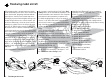
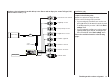
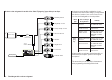

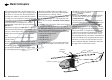
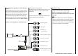

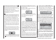

Table Of Contents
- Programming Manual 33116.mx-16 HoTT.1.gb
- Contents
- Safety Notes
- Safety notes and handling instructions relating to Nickel-Metal-Hydride rechargeable batteries
- Introduction
- Operating Notes
- Description of transmitter
- Using for the first time ...
- Installation Notes
- Definition of terms
- Assigning switches and control switches
- Digital trims
- “Binding” transmitter and receiver
- What is a mixer?
- General notes regarding freely programmable mixers
- Fixed-wing model aircraft
- Receiver socket assignment for "normal" models
- Receiver socket assignment for models of the “Delta / Flying wing” type
- “Binding” transmitter and receiver
- Detailed description of programming
- mx-16 HoTT programming techniques
- Model helicopters
- Receiver socket assignment
- “Binding” transmitter and receiver
- Detailed description of programming
- Programming example
- Appendix
- Guarantee certifi cate

47
Model helicopters: receiver assignment
Receiver socket assignment for model helicopters
Note for modellers upgrading from earlier Graupner
systems:
Compared with the previous receiver channel sequence,
servo socket 1 (collective pitch servo) and servo socket
6 (throttle servo) have been interchanged. The servos
must be connected to the receiver output sockets in the
order shown at bottom right. Outputs not required are
simply left vacant. For more information on the different
types of swashplate, please refer to the “Basic settings”
menu described on page 64 / 65.
All menus which are relevant to model helicopters are
marked with a “helicopter” symbol in the “Program
descriptions”:
This means that you can easily skip irrelevant menus
when programming a model helicopter.
Installation notes
The servos MUST be connected to the receiver
outputs in the order shown on this page:
Outputs not required are simply left vacant.
Please note the additional information on the follow-
ing pages.
Note:
To be able to exploit all the convenience and safety
features of the throttle limiter (see page 79), the speed
controller should be connected to receiver output “6”,
and not to receiver output “8”, as shown in the drawing
on the left. See page 97 for more details.
Se vo
4 8 V
C 577
Bes Nr 410
Receiver battery
Switch harness
Telemetry sensor
Y-lead,
Order No. 3936.11
Receiver
1 = PCollective pitch or roll-axis
(2) or pitch-axis (2) servo
2 = Roll-axis (1) servo
3 = Pitch-axis (1) servo
5 = Free, or pitch-axis (2) servo
4 = Tail rotor servo (gyro)
6 = Throttle servo
(speed controller)
7 = (Gyro gain)
8 = (Speed governor)