
User's Manual


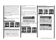


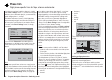
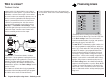

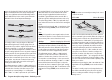
Table Of Contents
- Programming Manual 33116.mx-16 HoTT.1.gb
- Contents
- Safety Notes
- Safety notes and handling instructions relating to Nickel-Metal-Hydride rechargeable batteries
- Introduction
- Operating Notes
- Description of transmitter
- Using for the first time ...
- Installation Notes
- Definition of terms
- Assigning switches and control switches
- Digital trims
- “Binding” transmitter and receiver
- What is a mixer?
- General notes regarding freely programmable mixers
- Fixed-wing model aircraft
- Receiver socket assignment for "normal" models
- Receiver socket assignment for models of the “Delta / Flying wing” type
- “Binding” transmitter and receiver
- Detailed description of programming
- mx-16 HoTT programming techniques
- Model helicopters
- Receiver socket assignment
- “Binding” transmitter and receiver
- Detailed description of programming
- Programming example
- Appendix
- Guarantee certifi cate

86
Program description: Phase trim – fi xed-wing model
Phase trim
Flight phase-specifi c trims for fl aps, ailerons and elevator
If you wish to enter values other than “0”, e. g. to have
more lift at launch, or to be able to fl y more slowly
when thermalling, or faster when fl ying speed tasks, but
WITHOUT having to change the basic settings each
time, then you need to use alternative fl ight phases.
This is done by activating “Phase 2” and, if necessary,
“Phase 3” in the “Basic settings” menu. You might then
use “Phase 4” for the “thermal” settings.
This is accomplished by moving to the “Basic settings”
menu and assigning a switch to the selected phase or
phases. If you decide to use one of the three-position
switches SW 4/5 or 6/7 as the phase switch, then it is
advisable to assign it to the “Speed” phase and “Land-
ing” phase at the extremes, with “normal” at the centre
position. In our example phase 2 contains the “Launch”
settings, and since this has top priority, you can shift to
this phase from any other phase using a two-position
switch.
Notes:
At the centre position of SW 4/5 or 6/7 the switch •
symbols on the screen should look as in the picture
at top right.
Please note the priorities of the individual fl ight phas-•
es, as described in detail on page 60.
The default name for “Phase 2” is “take off”, that for
“Phase 3” is “speed”, and that for “Phase 4” is “landing”.
However, you can assign your own choice of names
at any time by selecting the appropriate line, pressing
the central SET button of the right-hand touch-key, and
selecting one of the f
ollowing names in the highlighted
fi
eld using the arrow buttons of the right-hand touch-key.
take off•
thermal•
If you have not assigned a switch to phases 2, 3 and 4
in the “Basic settings” menu, i. e. you have not assigned
switches to these alternative phases, you automatically
remain in fl ight phase 1 - “normal”.
The number and name (“normal”) of this fl ight phase
are permanently assigned, and cannot be altered. For
this reason the “normal” phase is not stated as Phase
1 “normal” in the “Basic settings” menu; it is simply
concealed.
10:01 2
phase 2
phase 3
phase 4
takeoff
landing
speed
–––
–––
–––
aile/flap 2aile
timer
If you select the “Phase trim” menu with this basic
arr
angement, you will fi nd just the “normal” line on the
screen, whose pre-set values of 0% are not usually
altered.
P H A S E T R I M
normal
¿
0%
0%
0%
AIL ELEFLA
Note:
In this menu you will have at least one control function
(ELE), and a maximum of three functions (ELE, AIL and
FLA), available for phase-specifi c trim settings, depend-
ing on the settings you have entered in the “Aileron /
fl ap” line of the “Basic settings” menu (see page 58).
dist(ance)•
speed•
acro•
landing•
air-tow•
test•
timer 10:01 2
phase 2
phase 3
phase 4
thermal
takeoff
speed
6
7
2
receiv out
These names will appear in the transmitter’s basic
display …
GRAUBELE
#01
2:22h
stop
flt
«normal »
0:00
0:00
5.5V
51%
5.2V
HoTT
M
… and in the “Phase trim” menu - see lo
wer picture.
Setting up fl ight phase trims
In the “Phase trim” menu you can adjust the trims for the
previously selected fl ight phases.
The fi rst step is to use the phase switch you have
already assigned to move to the phase which you wish
to adjust (the “
*
” at far left indicates the currently active
phase).