GRAVELY NAME: GRAVELY SNOWBLOWERS OPERATOR'S MANUAL PART NUMBER(S): 28” 34” 38” 44” - 20979 - 20981 - 20980 - 20982 The 28 Inch and 34 Inch Snowblowers are used with Gravely two wheel tractors. The 38 Inch and 44 Inch Snowblowers are used with Gravely four wheel tractors. To fasten the Snowblower to a Gravely two wheel tractor a Quick Hitch Pin Kit, part No. 23220, is needed. To fasten the Snowblower to a Gravely four wheel tractor a Front Drive Kit, part No. 21124, is needed.
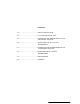
CONTENTS 1.0 ....................................................SAFETY PRECAUTIONS 2.0 ....................................................ILLUSTRATED PARTS LIST 3.0 ................................................... CONNECTING THE SNOWBLOWER TO THE TWO WHEEL TRACTOR 4.0 ....................................................OPERATING THE 28 or 34 INCH SNOWBLOWER 5.0 ................................................... CONNECTING THE SNOWBLOWER TO THE FOUR WHEEL TRACTOR 6.0 ...................................
1.0 SAFETY PRECAUTIONS The information in this Operator's Manual must be followed to do service and for safe operation of this equipment. Using this equipment the wrong way can cause injury to persons and damage to the equipment. Persons using or doing maintenance on this equipment must read this Operator's Manual and follow the instructions. It is important to understand that the warnings in this Operator's Manual and any other instruction book do not list every possible danger.
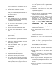
1.1 TRAINING 1. Read the Operator's Manual and learn the function of the tractor's controls. Know how to stop the tractor and snowblower drive fast. 2. Never let children operate the equipment. 3. Let adults operate the equipment only after reading and understanding the instructions in this Operator's Manual. 1.2 PREPARATION 1. Before snowfall, inspect the area of operation and remove all material that will be thrown, stop or do damage to the snowblower. 2.
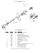
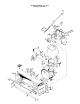
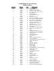
SNOWBLOWERS, 28”, 34", 38" & 44" FAN DRIVE SNOWBLOWERS, 28", 34", 38" & 44" FAN DRIVE ITEM NO. 1 2 3 4 5 6 7 8 9 10 11 12 13 14 15 16 PART NO. 419454 180044 20992 124553 20573 12134 14987 19731 19741 24560 20859 19740 21168 411027 20727 20728 QTY. 2 1 1 1 1 1 4 1 1 1 2 1 1 1 1 1 DESCRIPTION Nut, Lock; 1/4-20 Washer Insert Bolt, Hex; 1/4-20 x 2 Weldment, Drive Shaft Key, Woodruff; 1/4 x 1 Hard No. 15 Kit, Repair Universal Joint Neapco 1605x Kit, Repair Universal Joint Rockwell Std. Ring, Retaining; 1.
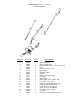
SNOWBLOWERS, 28", 34", 38" & 44" CRANK ASSEMBLY ITEM NO. PART NO. QTY. 1 2 3 4 5 6 7 8 9 10 11 12 13 14 15 16 20984 20999 19340 20989 456542 21144 20997 20998 9630 9612 10211 120396 137185 21005 21020 9652 21022 454563 10210 20985 1 1 1 1 2 1 1 1 2 1 1 1 1 1 1 1 1 1 1 1 17 18 19 DESCRIPTION Bracket, Support Spring, Compression Race, Bearing Thrust; 1.002 x 1.552 x .030 Shaft Pin, Spring; 3/16 x 1-1/2 Eye, Single Assembly, Cable Support Clamp, Hose SAE; Type F Connector Grip, Handle Washer, Flat; .
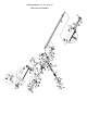
SNOWBLOWERS, 28", 34", 38" & 44" REEL DRIVE ASSEMBLY
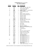
SNOWBLOWERS, 28”, 34”, 38” & 44” REEL DRIVE ASSEMBLY ITEM NO. 1 2 3 4 5 6 7 8 9 10 11 12 13 14 15 16 17 18 19 20 21 22 23 24 25 26 27 28 29 30 31 32 PART NO. QTY. 120392 6341 6339 9660 9659 20696 10325 9662 9661 20697 6485 11796 19794 103880 426767 10573 9668 12399 9657 181666 9667 12404 12401 12402 12403 274655 10579 120423 9669 12400 20699 10222 11797 19795 20698 10221 11802 19799 6494 6493 4 1 1 2 1 1 1 2 1 1 1 1 1 1 2 1 2 2 2 2 1 2 1 1 1 2 1 3 1 1 1 1 1 1 1 1 1 1 1 2 DESCRIPTION Washer, Flat; .
SNOWBLOWERS, 28" & 34" FRAME ASSEMBLY
SNOWBLOWERS, 28" & 34" WALKING FRAME ASSEMBLY ITEM NO. 1 2 3 4 5 6 7 8 9 10 11 12 13 14 15 16 17 18 19 20 21 22 23 24 25 26 27 22 29 30 31 32 33 34 35 36 37 38 39 40 41 42 43 44 45 46 47 48 49 50 51 52 53 PART NO.
SNOWBLOWERS, 38" & 44" FRAME ASSEMBLY
SNOWBLOWERS, 38" & 44" FRAME ASSEMBLY ITEM NO. PART NO.
3.0 CONNECTING THE SNOWBLOWER TO THE TWO WHEEL TRACTOR 1. Install the Quick Hitch Pin Kit as shown in figure 3.0-1. 8. Put the ring pin through the hole in the end of the quick hitch pin as shown in figure 3.0-2. f 1 -Quick Hitch Pin 2 - Bolt 3 -Attachment Adapter 4 --- Bushing Figure 3.0-1 2. Put the bushing on the 1/2" x 2-3/4" Bolt and fasten to the upper, left quick hitch stud as shown in figure 3.0-1. 3. Apply multi-purpose grease to the quick hitch pin and power take-off (PTO) shaft on the tractor.
4.0 OPERATING THE 28 & 34 INCH SNOWBLOWERS Read the tractor Operator's Manual. Know how to operate the tractor controls. 1. Adjust the skids shown in figure 4.0-1 to give ground clearance needed for the surface conditions. When removing snow from a gravel surface, adjust the skids to raise the snowblower to prevent gravel from going into the snowblower. When removing snow from a smooth surface, the snowblower can be lowered until the wearstrip contacts the surface.
NOTE: When going through the snow for the first time, a full width passage must be cut. The forward speed must be slow enough to permit the snow to go through the discharge chute without being stopped. 5.0 CONNECTING THE SNOWBLOWER TO THE FOUR WHEEL TRACTOR 1. Install the front drive kit on the tractor. See figure 5.0-1. 9. Put the Direction Control Lever in the forward position and make the first passage through the snow.
3. Put the frame pivot rod of the snowblower support in the front attachment brackets and fasten with the hitch pins as shown in figure 5.0-3. 1. 2. 3. 4. 5. Frame Pivot Rod Front Attachment Bracket Hitch Pin Universal Joint Shaft Universal Joint Tube Figure 5.0-3 4. Put the universal joint shaft into the universal joint tube and put the universal joint shaft on the drive shaft of the front drive kit as shown in figure 5.0-3. 5.
6.0 OPERATING THE 38 & 44 INCH SNOWBLOWERS Read the tractor Operator's Manual. Know how to operate the tractor controls. 1. Adjust the skids shown in figure 6.0-1 to give ground clearance needed for the surface conditions. When removing snow from a gravel surface, adjust the skids to raise the snowblower to prevent gravel from going into the snowblower. When removing snow from a smooth surface, the snowblower can he lowered until the wearstrip contacts the surface. I - Discharge Chute Crank Figure 6.0-2. 7.
11. On the next and remaining passages, cut as much snow as will go through the discharge chute without being stopped. 12. If the reel stops turning while the fan continues to turn, disengage the PTO, stop the engine and tighten the nuts on each end of the reel shown in figure 6.0-3 to a torque of 85 ft. lbs. (115 Nm). 8.0 STORAGE 1. Clean the Snowblower. 1. Check the gear housing lubricant level by removing the pipe plug shown in figure 8.0-I.
GRAVELY ATTACHMENT LIMITED WARRANTY This Limited Warranty is issued by Gravely Division, McGraw-Edison Company, and consists of the following terms: 6. This Warranty does not cover the following: 1. Only the original purchaser of new Gravely manufactured attachments is covered by this Warranty. a. Transportation between owner's home or place of business and the dealership. If the dealer provides the transportation of the attachment, he will charge the owner his usual rate for such service. 2.