Pro Unit Owner/Operator Manual Models 988100 - GR1336FX 988101 - GR1536FX 988102 - GR1548FX 988103 - GR1548FL 988104 - GE1748FL 988110 - GR1332FX 988112 - GR1544FX 988114 - GR1336FXP 988115 - GR1548FXP 988118 - GR1332FXP 988119 - GR1544FXP 988313 - GR1332FXPCE ENGLISH FRANÇAIS ESPAÑOL 04941300 7/03 Printed in USA
MODEL DECLARATION OF CONFORMITY ISSUED BY THE MANUFACTURER CERTIFICAT DE CONFORMITÉ DU MODÈLE DÉLIVRÉ PAR LE FABRICANT VOM HERSTELLER AUSGESTELLTE MODELL-ÜBEREINSTIMMUNGSERKLÄRUNG MODELCERTIFICAAT VAN OVEREENSTEMMING AFGEGEVEN DOOR DE FABRIKANT DICHIARAZIONE DI CONFORMITÀ DEL PRODOTTO REALIZZATA DAL PRODUTTORE MODELO DE DECLARACIÓN DE CONFORMIDAD EMITIDA POR EL FABRICANTE MODEL KONFORMITETSERKLÆRING UDSTEDT AF FABRIKANTEN MODELLENS SAMSVARSERKLÆRING UTFERDIGET AV PRODUSENTEN FÖRSÄKRAN OM MODELLÖVERENSSTÄMME
Stated Sound Power Levels are established following Annex VIII “Full Quality Assurance” of directive 2000/14/EC. Les déclarations de niveau de puissance acoustique sont établies conformément à l’Article VIII « Assurance qualité totale » de la directive 2000/14/EC. Die angegebenen Geräuschpegel wurden gemäß Anhang VIII „Totales Qualitäts-Management“ der EU-Richtlinie 2000/14/EC.
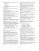
CONTROLS AND FEATURES 13 8 7 3 3 7 9 18 17 12 18 11 4 10 5 1 OG1765 14 12 2 6 7 13 OG1730 8 7 9 3 16 11 5 15 3 14 10 4 1 OG0742 Figure 1 ENGLISH 1. Shift Lever 2. Steering Lever Latches (988100, 101, 102, 103, 104, 110, 112) 3. Steering Levers (988100, 101, 102, 103, 104, 110, 112) Control Levers (988114,115, 118, 119, 313) 4. Throttle Lever (988101, 102, 103, 104, 112, 115, 119) Throttle-Choke Lever (988100, 114, 110, 118, 313) 5. Ignition Switch 6. PTO Switch 7.
TABLE OF CONTENTS Controls and Features . . . . . . . . . . . . . . . . . . . . . 4 Storage. . . . . . . . . . . . . . . . . . . . . . . . . . . . . . . . . 25 Safety . . . . . . . . . . . . . . . . . . . . . . . . . . . . . . . . . . . 6 Troubleshooting . . . . . . . . . . . . . . . . . . . . . . . . . 25 Assembly . . . . . . . . . . . . . . . . . . . . . . . . . . . . . . . 10 Accessories . . . . . . . . . . . . . . . . . . . . . . . . . . . . . 26 Operation . . . . . . . . . . . . . . . . . . . . .
5. Explain recommended lubrication and maintenance. Advise customer on adjustments. 6. Instruct customer on controls and operation of unit. Discuss and emphasize the Safety Precautions. Give customer Owner/Operator, Parts, and Engine Manuals. Advise customer to thoroughly read and understand them. SAFETY NOTATIONS WARNING: This cutting machine is capable of amputating hands and feet and throwing objects.
1 2. Danger! Rotating Blades TO AVOID SERIOUS INJURY OR DEATH: • Read the operator's manual. • Keep children and others away from unit while operating. • Never direct discharge toward other people. Thrown objects can cause injury. • Keep safety devices (guards, shields, switches, etc.) in place and working. • Check interlock system per manual before use. • Never allow operation by untrained persons. • When parking on a slope always engage parking brake.
Complete a walk around inspection of unit and work area to understand: • Work area • Your unit • All safety decals ALWAYS check overhead and side clearances carefully before operation. ALWAYS be aware of traffic when operating along streets or curbs. Keep children and people away. Keep children out of work area and under watchful care of a responsible adult. Keep area of operation clear of all toys, pets, and debris. Thrown objects can cause injury. Check for weak spots on docks, ramps or floors.
Disengage PTO when attachment is not in use. DO NOT raise deck with blades running. ALWAYS turn off power to attachment when travelling, crossing driveways, etc. Avoid uneven and rough terrain. DO NOT operate near drop offs, ditches, or embankments. Unit can suddenly turn over if a wheel is over the edge of a cliff or ditch, or if an edge caves in. DO NOT try to stabilize unit by putting foot on ground when operating with applicable riding attachments.
DO NOT TIP battery beyond a 45° angle in any direction. ALWAYS keep batteries out of reach of children. Before making any inspections, repairs, etc.: disengage PTO, stop unit and engine, remove key, allow moving parts to stop. Allow hot parts to cool. ALWAYS block wheels, engage parking brake and know all jack stands are strong, secure and will hold weight of unit during maintenance. An extension spring, when extended, stores energy and can be dangerous.
Steering Levers (988100, 101, 102, 103, 104, 110, 112) Throttle Lever (988101, 102, 103, 104, 112, 115, 119) The throttle lever changes the speed of the engine. Move the throttle lever to Fast (1) to increase engine speed. Move the lever to Slow (2) to decrease engine speed. 1 WARNING: AVOID INJURY. When the engine is running and the shift lever is engaged, releasing only one steering latch causes the unit to circle around one drive wheel.
FILL FUEL TANK PTO Clutch (988114, 115, 118, 119, 313) WARNING: Fuel is highly flammable and its vapors are explosive. Handle with care. Use an approved fuel container. NO smoking, NO sparks, NO flames. ALWAYS allow engine to cool before servicing. NEVER fill fuel tank when engine is running or hot from operation. NEVER fill or drain fuel tank indoors. Replace fuel cap securely and clean up spilled fuel. 1 2 3 OE0261 Pull the PTO (power take off) switch past On (1) to Reset (2) to engage the mower blades.
6. Grasp recoil starter handle and pull rope out slowly until it pulls harder. This is the compression stroke. 7. Let the rope rewind slowly. 8. Pull rope with rapid continuous full arm stroke to start engine. Allow rope to rewind slowly. IMPORTANT: DO NOT let starter handle snap against engine. 9. Repeat until engine starts. (If engine does not start, refer to Engine Manual.) 10. After engine starts, adjust choke as needed. Allow engine to warm and run smoothly before operating unit.
WARNING: AVOID INJURY. When the engine is running and the shift lever is engaged, releasing only one steering latch causes the unit to circle around one drive wheel. ALWAYS hold both steering levers in the neutral position when releasing the steering lever latches. ALWAYS release levers slowly. • WARNING: Uncontrolled reverse travel can result in serious injury. Do not put shift lever into the reverse position unless you are prepared to operate in reverse.
• To move straight forward, slowly push control levers forward. OG1600 • To stop unit motion, allow control levers to return to neutral. OG1610 • To turn to the left, push the right hand control lever forward. OG1630 • To turn to the right, push the left hand control lever forward. NOTE: Operator presence control must remain engaged. 4. Move the PTO switch to On to engage mower. IMPORTANT: NEVER engage the PTO if the mower is plugged with grass or other material. This will damage the PTO belt. 5.
NOTE: It may be necessary to adjust cutting height in steps to keep deck from binding. 1 (25) 1.5 (38) 2 (51) 2.5 (64) 3 (76) 3.5 (90) 4 (102) Figure 6 988100, 101, 102, 103, 104, 110, 112 To move the unit without the engine running: 1. Put the shift lever in neutral. 2. Hold steering levers in neutral and disengage latches. Release steering levers. The brake is disengaged when the steering levers are released. 3. Push unit to desired location. IMPORTANT: Towing the unit will damage transmission.
MAINTENANCE 3. Disengage PTO. The engine MUST stop whenever the operator removes both hands from controls while the PTO or transmission is engaged. To test: 1. Start engine and engage PTO. 2. Release operator presence control lever(s). Engine must stop. 3. Disengage PTO. 4. Restart engine. 5. Place shift lever in Forward. 6. Release operator presence control lever. Engine must stop. WARNING: AVOID INJURY. Read and understand the entire Safety section before proceeding.
CHECK BATTERY (988104) GENERAL LUBRICATION Apply a small amount of oil to the pivot points as required for smooth operation (Figure 7). Apply high quality lithium based grease to all lube fittings every 50 hours of operation. NOTE: The mower spindle assembly is maintenance free. WARNING: AVOID INJURY. Read and understand the entire Safety section before proceeding.
6. Reinstall the clevis pin and hair pin. 7. Repeat for other steering lever. 5. Adjust tracking if needed. Try each of the following steps until the unit tracks straight. It may not be necessary to perform all the steps. If unit turns to the right: 1. Reduce the air pressure in the left tire. 2. Increase the air pressure in the right tire. 3. Check for brake binding on right wheel and adjust as needed. If unit turns to the left: 1. Reduce the air pressure in the right tire. 2.
Note: 988100 Shown. 988114, 115, 118, 119, 313 Similar. 1 Wing Nut 2 Brake Rod 3 4 5 Brake Band 7 6 Note: Some components removed for clarity. Figure 9 8 9 OG0751 1. 2. 3. 4. Handlebar Steering Lever Steering Control Rod Wheel Clutch Arm Weldment 5. Brake Rod OG1350 REPLACE TRACTION BELTS 1. Turn off the engine, remove the key and allow unit to cool. 2. Release the steering levers (988100, 101, 102, 103, 104, 110, 112). 3. Raise the rear of the unit so that the drive wheels are off the ground.
ADJUST SHIFT LEVER LINKAGE WARNING: AVOID INJURY. An extension spring, when extended, stores energy and can be dangerous. Always use tools specifically designed for installing or removing an extension spring. Always compress or extend springs slowly. The transmission shift lever is attached to the transmission shift arm with two 5/16-18 bolts (Figure 11). 2 1 4. Loosen one and remove one front engine bolt. Save the hardware. 5. Turn the clutch bracket away from the clutch. 6.
3. Repeat for each inspection slot. To adjust: 1. If necessary, loosen gap adjustment nuts until a .005" feeler gauge fits between armature and rotor. 2. Slide a .012" feeler gauge between armature and rotor. 3. Tighten gap adjustment nut until there is slight contact on feeler gauge. 4. Repeat steps 1 – 3 at each inspection slot. NOTE: Adjust air gap as evenly as possible. 5. Start unit, engage and disengage PTO. 6. Shut off unit. 7. Recheck air gap and adjust if needed.
44"AND 48" BELT REPLACEMENT 5. Make the final jumper cable connection to the engine block or the furthest ground point away from the discharged battery. Mower Drive Belt WARNING: Make sure cables are clear of any moving engine parts before starting engine. 6. Start engine (See Starting and Shut Off on page 12). If engine will not start after several tries, unit or battery may need service. 7. After engine starts, leave cables connected for one to two minutes. 8. Disconnect cables in reverse order. 9.
MOWER BLADES Replace 1. Put the blades, flat washers, lock washers, and the bolts back on the spindle shafts. 2. Tighten the bolts to a torque of 115-125 lbf-ft (156-169.5 N•m). 3. Replace ignition wire on spark plugs. NOTE: If mower is used under sandy soil conditions, replace blades when air lifts become eroded through at ends (Figure 18). DO NOT sharpen to this pattern Sharpen the Mower Blades Figure 18. CAUTION: DO NOT sharpen mower blades while on unit.
STORAGE NOTE: Clean unit thoroughly with mild soap and low pressure water and lubricate (see Maintenance). Touch up all scratched painted surfaces. Do not allow gasoline or oil to remain on any decals. WARNING: AVOID INJURY. Read and understand the entire Safety section before proceeding. Engine Storage – Two Months or More Check each item in the Maintenance Schedule on page 17, but do not add gasoline. Clean the unit. Touch up all scratched painted surfaces.
PROBLEM PROBABLE CAUSE CORRECTION Unit pulls sharply to the left or right when the speed control levers are quickly moved all the way forward Unit does not straighten immediately when the steering levers are released 1. Steering levers out of adjustment. 1. See Adjust Steering Levers on page 19. Unit loses power 1. Binding in the steering or brake linkage. 1. Check linkage for debris or damage. Repair if necessary. See Adjust Brakes on page 19 or your Dealer for repairs. 2.
SPECIFICATIONS Model Number Description Length – in (cm) 988100 988101 988102 988103 988104 988110 GR1336FX GR1536FX GR1548FX GR1548FL GE1748FL GR1332FX 79.75 (202.5) 73.5 (186.7) Height – in (cm) 77 (195.6) 79.75 (202.5) 42 (106.7) Width – in (cm) 38.12 (96.8) Actual Weight – lbs (kg) 511 (232.3) Battery 50.58 (128.47) 560 (254.5) N/A Brakes 35.3 (89.7) 627 (285) 500 (226.8) 12V 255 CCA N/A Kawasaki FH500V-BS35 Kawasaki FH381V-BS04 17 (12.7) 13 (9.
SPECIFICATIONS Model Number 988112 988114 988115 988118 988119 988313 Description GR1544FX GR1336FXP GR1548FXP GR1332FXP GR1544FXP GR1332FXPCE Length – in (cm) 75.5 (191.8) 80.25 (203.8) 77.5 (196.9) 80.25 (203.8) 76.0 (193.0) 80.25 (203.8) Height – in (cm) 42 (106.7) Width – in (cm) 47.0 (119.38) 38.2 (97.0) 50.58 (128.47) 35.3 (89.7) 47.0 (119.38) 35.3 (89.7) 560 (254.5) 530 (240.9) 579 (263.2) 519 (235.4) 579 (263.2) 519 (235.
2-Year Limited Warranty Gravely Division of Ariens Company 655 West Ryan Street P.O. Box 157 Brillion, WI 54110-0157 920-756-2141 Fax 920-756-2407 www.gravely.com Gravely Division of Ariens Company (Gravely) hereby warrants to the original consumer purchaser that all Gravely Two-Wheel, Professional G, Pro, and ProMaster products will be free from defects in material and workmanship for a period of two (2) years from the date of purchase or 1000 hours, whichever comes first.
GRAVELY A Division of Ariens Company 655 West Ryan Street P.O. Box 157 Brillion, WI 54110-0157 920-756-2141 Fax 920-756-2407 www.gravely.