
Instruction Manual

Grayhill, Inc. • 561 Hillgrove Avenue • LaGrange, Illinois 60525-5997 • USA • Phone: 708-354-1040 • Fax: 708-354-2820 • www.grayhill.com
DIP Switches
SERIES 94R
Economical, Binary Coded
FEATURES
• 10,000CyclesofOperation
• Gold-PlatedContacts
• SealedContactSystem
• RightAngleMount
• Octal,BCD&HexadecimalCodes
• StandardorComplement
• RoHSCompliant
SPECIFICATIONS:
Electrical Ratings
Make-and-break Current Rating:30mAat30
Vdcfor10,000cyclesofoperation.
Carrying Current Rating:100mAat50Vdc
Contact Resistance: 50 mohms maximum
initially (measured at 10 mA, 50 mVdc).
150mohmsmaximumafterlife.
Insulation Resistance:(measuredat100Vdc
acrossopenswitchcontacts)
Initial:5000Mohmsminimum.AfterLife:1000
Mohmsminimum.
Dielectric Strength:(measuredacross
openswitchcontacts)Initial:500VacRMS
minimum.AfterLife:250VacRMS
Mechanical Ratings
Mechanical Life:10,000cycles of operation.
Onecycleisarotationthroughallpositionsand
acompletereturnthroughallpositions.
Mechanical Shock: 1000g's,0.5mS,halfsineper
MIL-STD-202F,Method213,TestConditionE.
Vibration Resistance:10-2000Hzat15Gor
0.060" double amplitude per MIL-STD-202F,
Method204,TestConditionB.
Operational Torque:2to6inch-ouncesinitially
and1.2inch-ouncesminimumafterlife.
Environmental Ratings
Operating Temperature Range: -40° to
+85°C.
Storage Temperature Range:-40°to+85°C.
Moisture Resistance: 240 hours with
temperature cycling and polarization. Passes
insulation resistance and dielectric strength
per MIL-STD-202F, Method 106 following
exposure.
Materials and Finishes
Rotor and Switch Body:Plastic(UL94V-O)
Contact Material: Copper alloy plated.
30 microinches minimum gold over 50
microinchesminimumnickel.
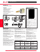
CODE & TRUTH TABLES:
DIMENSIONS ininches(andmillimeters)
Unlessotherwiseindicated,tolerancesare±.010(0,25)
S W I T C H P O S I T I O N
CODEOUTPUT CODEOUTPUT
8 8412
0
1
2
3
4
5
6
7
8
9
A
B
C
D
E
F
412
Standard
Output
Complement
Output
Dot indicates ter minal to common
connection. All switches are continuous
rotation.
OctalandOctalComplementoutputsare
0thru7positions.
BCDandBCDComplementoutputsare0
thru9positions.
H ex a d e c i m a l a nd He x a d e c i m al
Complement outputs are 0 thru F
positions.
Standard codes have natural color
rotors; complements have rotors in a
contrastingcolor.
Shorting Member: Copper alloy plated.
30 microinches minimum gold over 50
microinchesminimumnickel.
Terminals: Copperalloy,mattetinplatedover
nickelbarrier.
Internal O-ring:RubberBUNA-N
Soldering Information
*For the most current soldering & cleaning processing
guidelines, reference Grayhill Dip Switch Processing
Information, Bulletin 1234
Soldering Temperature:260°Cmaximum.
Cleaning: Acceptable solutions include
1-1-1 Trichlorenthane, Freon (TF, TE, or
TMS), Isopropyl Alcohol and detergent
(140°F maximum). Solutions which are not
recommended include Acetone, Methylene
Chloride,andFreonTMC.
ORDERING INFORMATION: Series 94R
Continuous Rotation Versions
No. of Standard Code Complement
Code Positions Part Number Part Number
Octal 8 94RB08CT 94RC08CT
BCD 10 94RB10CT 94RC10CT
Hexadecimal 16 94RB16CT 94RC16CT
Rotational Stop Versions*
No. of Standard Code Complement
Code Positions Part Number Part Number
Hexadecimal 16 94RB16FT 94RC16FT
* ConsultGrayhillfor8or10position
Rotary DIP Switches
.213
(5,41)
.433
(11,00)
.443
(11,25)
.480
(12,19)
.286
(7,26)
.689 (17,50).210 (5,33)
.200 (5,08)
1.123 (28,52)
.044 (1,12)
DIA.
.179
(4,55)
.094
(2,93)
.162
(4,11)
.059
(1,50)
.058 (1,47)
DIA.
.199 (5,05)
.235 (5,97)
8
C
2
1
C
4
PC board layout
as viewed from the
top of the switch
Pin #1