
Manual

as shown in the wiring schematic, Figure 2. All electri-
cal work must be according to applicable codes.
9.Complete any other necessary installations to finish the
hook up. This includes attaching hoses and fittings
(customer-supplied) from the pump discharge to the
machine tool. The 35-gallon BFCT40 system has a 3/8"
pump discharge; the 90-gallon BFCT80 system has a
1/2" pump discharge. Do not reduce the outlet of the
pump. Doing so will reduce the flow capacity of the
pump. Also plumb the return lines so they are discharg-
ing directly onto the diffuser plate of the Bed Filter or
intake of the Magnetic Separator.
10. Turn on system and monitor operation to make sure
all connections are tight and fluid circulation is func-
tioning. Watch as the coolant drains from the machine
tool back into the collection tank. Make sure that it is
flowing freely. Check rotation of pump. Rotation
should be in a clockwise direction looking down on the
motor (match arrow on pump body).
11. Make any final adjustments to float switch to ensure
level of liquid in filter bed does not exceed height of
chain on either side. To adjust the liquid level, turn the
screw on the floating ball switch. To lower the level,
turn clockwise. To raise the level, turn counter-clock-
wise.
Optional Magnetic Separator
With Bed Filter
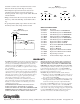
1.Verify operating voltage and make any necessary
changes to the connections located on the underside of
the Magnetic Separator - the unit is a dual voltage sys-
tem and the default setting should be 230V, 3Ph.
Follow the wiring schematic (Figure 3) to check/
change the power settings. All electrical work must be
according to applicable codes.
2.Remove solid cover plate from end of bed filter to
expose frame rails.
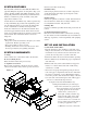
3.Position the Magnetic Separator as shown in Figure 1.
Make sure mounting feet are resting on the metal sup-
ports of the bed filter and the mounting holes are cen-
tered on those supports. The discharge chute should be
pointing into the Sludge Box.
4.Use self tapping screws to fasten the Magnetic
Separator to the support rails.
5.Plumb the outlet of the Magnetic Separator so that the
flow is routed back into the center of the diffuser tray
where it can be run through the filter media. Plug the
outlet port that is not being used with the fitting provided.
6.Visually inspect scraper blade so it is just lightly touching
the surface of the magnetic roller.
7.Complete the electrical connections and make final
adjustments.
Without Bed Filter
1.Verify operating voltage and make any necessary
changes to the connections located on the underside of
the Magnetic Separator - the unit is a dual voltage sys-
tem and the default setting should be 230V, 3Ph.
Follow the wiring schematic (Figure 3) to check/
change the power settings. All electrical work must be
according to applicable codes.
2.Remove the intake trough and plumbing from the small
tank lid.
3.Positioning the Magnetic Separator on the tank is not
critical and optimal location is at the discretion of the
operator. We recommend that the discharge chute hangs
over the side of the tank directing refuse directly into
the plastic tray provided with the magnetic separator.
4.Use self tapping screws to fasten the Magnetic
Separator to the tank lid.
5.Plumb the outlet of the Magnetic Separator so that the
flow is routed back into the tank. Plug the outlet port
that is not being used with the fitting provided.
6.Complete the electrical connections and make final
adjustments to suit your application.
MAINTENANCE
Be sure power to the unit is shut off before per-
forming maintenance on your machinery.
• For continued service, have an extra roll of filter media
available.
• Replace the used filter media before you reach the end
of the roll to avoid letting the uncleaned coolant flow
directly into the tank.
• Make sure that pump is spinning freely. Hold shaft and
spin to check. If necessary, remove bottom cap and
impeller, clean volute cavity to remove obstructions.
Replace impeller and bottom cap.
• Periodically check and wipe clean the baffling screen
that is inside of coolant tank below the pump compart-
ment.
• Check and clean the diffuser tray (D) frequently to
keep coolant flowing into the bed filter.
• Be sure to dispose of the drained sludge from the
sludge collection box before it is full.
• Dispose of used media according to all federal, state
and local regulations.
• If you are using a Magnetic Separator, check it fre-
quently and dispose of metal debris. Check the scraper
to be sure it is cleaning the roller. Scraper should make
only light contact with the surface of the roller. Use
wing nuts to make adjustments, loosening to decrease
pressure on the scraper. Clean sludge from the scraper