
User guide


795-92645 03-13 Bed Filter/Magnetic Separator OMI
10 Turn on system and monitor operation to make sure all
connections are tight and fluid circulation is functioning.
Watch as the coolant drains from the machine tool back into
the collection tank. Make sure that it is flowing freely. Check
looking down on the motor (match arrow on pump body).
11 Make any final adjustments to float switch to ensure level of
liquid in filter bed does not exceed height of chain on either
side. To adjust the liquid level, turn the screw on the floating
ball switch. To lower the level, turn clockwise. To raise the
level, turn counter-clockwise.
OPTIONAL MAGNETIC SEPARATOR
With Bed Filter
1 Verify operating voltage and make any necessary changes
to the connections located on the underside of the Magnetic
Separator—the unit is a dual voltage system and the default
setting should be 230V, 3Ph. Follow the wiring schematic
(Figure 3) to check/change the power settings. All electrical
connections should conform to national/local codes and be
made by qualified personnel.
2
frame rails.
3 Position the Magnetic Separator as shown in Figure 1. Make
sure mounting feet are resting on the metal supports of the
bed filter and the mounting holes are centered on those
supports. The discharge chute should be pointing into the
Sludge Box.
4 Use self tapping screws to fasten the Magnetic Separator to
the support rails.
5 Plumb the outlet of the Magnetic Separator so that the flow is
routed back into the center of the diffuser tray where it can
be run through the filter media. Plug the outlet port that is not
being used with the fitting provided.
6 Visually inspect scraper blade so it is just lightly touching the
surface of the magnetic roller.
7 Complete the electrical connections and make final
adjustments.
Without Bed Filter
1 Verify operating voltage and make any necessary changes
to the connections located on the underside of the Magnetic
Separator - the unit is a dual voltage system and the default
setting should be 230V, 3Ph. Follow the wiring schematic
(Figure 3) to check/ change the power settings. All electrical
work must be according to applicable codes.
2
3 Positioning the Magnetic Separator on the tank is not critical
and optimal location is at the discretion of the operator.
We recommend that the discharge chute hangs over the
side of the tank directing refuse directly into the plastic tray
provided with the magnetic separator.
4 Use self tapping screws to fasten the Magnetic Separator to
the tank lid.
5 Plumb the outlet of the Magnetic Separator so that the flow
is routed back into the tank. Plug the outlet port that is not
being used with the fitting provided.
6 Complete the electrical connections and make final
adjustments to suit your application.
MAINTENANCE
Be sure power to the unit is shut off before performing
maintenance on your machinery.
available.
the roll to avoid letting the uncleaned coolant flow directly
into the tank.
cap.
keep coolant flowing into the bed filter.
collection box before it is full.
local regulations.
and dispose of metal debris. Check the scraper to be sure
it is cleaning the roller. Scraper should make only light
contact with the surface of the roller. Use wing nuts to make
adjustments, loosening to decrease pressure on the scraper.
Clean sludge from the scraper and roller so that it does not
harden and cause a malfunction. Clean away metal chips as
necessary.
period of time, loosen the wing nuts to decrease pressure of
the scraper on the roller. This will extend roller life.
tray, chain and tank. Wipe out all debris with a rag.
machinery with a clean, damp cloth as needed.
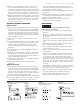
W2 U2 V2
U1 V1 W1
230V
RED BLUE BROWN
BLACK
YELLOW WHITE
W2 U2 V2
U1 V1 W1
460V
W2 U2 V2
U1 V1 W1
230V
RED BLUE BROWN
BLACK
YELLOW WHITE
W2 U2 V2
U1 V1 W1
460V
Figure 3
Wiring diagram for Magnetic
Separator (inside unit)
Figure 2 Wiring diagram for Bed Filter
BFTS40, 80, 120 BFTS160
Figure 4
Wiring diagram for full system