795–90653 GM 2–01 Graymills ALUMINUM Air-Operated Double Diaphragm Pumps 1” Model Operations and Maintenance Instructions WARNING/CAUTIONS Read all these SAFETY INSTRUCTIONS BEFORE installing or using this equip– ment. Keep this manual handy for refer– ence/training. US and Foreign Patents Pending 1” Aluminum Model 02632 Graymills Corporation 3705 N. Lincoln Avenue Chicago, Illinois 60613 773/248–6825 FAX 773/477–8673 www.graymills.
Table of Contents Symbols . . . . . . . . . . . . . . . . . . . . . . . . . . . . . . . . . . . . . . 2 Safety Warnings . . . . . . . . . . . . . . . . . . . . . . . . . . . . . . . 2 Installation . . . . . . . . . . . . . . . . . . . . . . . . . . . . . . . . . . . . . 5 Operation . . . . . . . . . . . . . . . . . . . . . . . . . . . . . . . . . . . . 11 Maintenance . . . . . . . . . . . . . . . . . . . . . . . . . . . . . . . . . . 12 Troubleshooting . . . . . . . . . . . . . . . . . . . . . . . . . . . .
WARNING EQUIPMENT MISUSE HAZARD Any misuse of the equipment or accessories, such as overpressurizing, modifying parts, using incompatible chemicals and fluids, or using worn or damaged parts, can cause them to rupture and result in splashing in the eyes or on the skin, other serious injury, or fire, explosion or property damage. D This equipment is for professional use only. Observe all warnings. Read and understand all instruction manuals, warning labels, and tags before you operate this equipment.
SAFETY PRECAUTIONS CAUTION D Verify the chemical compatibility of the pump wetted parts and the substance being pumped, flushed or recirculated. Chemical compatibility may change with temperature and concentration of the chemical(s) within the substance being pumped, flushed or recirculated. D The pump should not be used for the structural support of the piping system. Be certain system components are properly supported to prevent stress on the pump parts.
Installation General Information D The Typical Installations shown in Figs. 2–4 are only guides for selecting and installing system components. Contact Graymills for assistance in planning a system to suit your needs. D Always use Genuine Graymills Parts and Accessories. D Reference numbers and letters in parentheses refer to the callouts in the figures and the parts list.
Installation Mountings b. Locate one bleed-type master air valve (B) close to the pump and use it to relieve trapped air. See the WARNING above. Locate the other master air valve (E) upstream from all air line accessories and use it to isolate them during cleaning and repair. c. The air line filter (F) removes harmful dirt and moisture from the compressed air supply. CAUTION The pump exhaust air may contain contaminants. Ventilate to a remote area if the contaminants could affect your fluid supply.
Installation Fluid Outlet Line 1. Use grounded fluid hoses (L). The pump fluid outlet (S) is 1” npt(f). See Fig. 5. Screw the fluid fitting into the pump outlet securely. 2. Install a fluid drain valve (J) near the fluid outlet. See the WARNING at left, and Figs. 2–4 on pages 8 and 9. 3. Install a shutoff valve (K) in the fluid outlet line. WARNING A fluid drain valve (J) is required to relieve pressure in the hose if it is plugged.
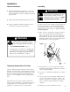
Installation Figure 2 KEY FOR FIG. 2 A B C D E F G H J K L Y TYPICAL BUNG-MOUNT INSTALLATION Air supply line Bleed-type master air valve (required for pump) Air regulator Air line quick disconnect Master air valve (for accessories) Air line filter Fluid suction line Bung adapter Fluid drain valve (required) Fluid shutoff valve Fluid line Ground wire (required; see page 5 for installation instructions) E F C B A K L D J Y H G 02648 Figure 3 TYPICAL FLOOR-MOUNT INSTALLATION KEY FOR FIG.
Installation Figure 4 KEY FOR FIG.
Installation Air Exhaust Ventilation The air exhaust port is 3/4 npt(f). Do not restrict the air exhaust port. Excessive exhaust restriction can cause erratic pump operation. WARNING FIRE AND EXPLOSION HAZARD Be sure to read and follow the warnings and precautions regarding HAZARDOUS FLUIDS, and FIRE OR EXPLOSION HAZARD on pages 2 and 3, before operating this pump. To provide a remote exhaust: Be sure the system is properly ventilated for your type of installation.
Operation Pressure Relief Procedure WARNING PRESSURIZED EQUIPMENT HAZARD The equipment stays pressurized until pressure is manually relieved. To reduce the risk of serious injury from pressurized fluid, accidental spray from the gun or splashing fluid, follow this procedure whenever you D D D D 5. Close the fluid drain valve (J). 6. Back out the air regulator (C) knob, and open all bleed-type master air valves (B, E). 7.
Maintenance Lubrication Tightening Threaded Connections The air valve is designed to operate unlubricated, however if lubrication is desired, every 500 hours of operation (or monthly) remove the hose from the pump air inlet and add two drops of machine oil to the air inlet. Before each use, check all hoses for wear or damage, and replace as necessary. Check to be sure all threaded connections are tight and leak-free. Check and retorque all threaded connections at least every two months.
Troubleshooting WARNING To reduce the risk of serious injury whenever you are instructed to relieve pressure, always follow the Pressure Relief Procedure on page 11. D Relieve the pressure before checking or servicing the equipment. D Check all possible problems and causes before disassembling the pump. PROBLEM CAUSE SOLUTION Pump cycles at stall or fails to hold pressure at stall. Worn check valve balls (301), seats (201) or o-rings (202). Replace. See page 17.
Troubleshooting PROBLEM CAUSE SOLUTION Fluid in exhaust air. Diaphragm ruptured. Replace. See pages 18–20. Loose diaphragm shaft bolt (107). Tighten or replace (pages 18–20). Damaged o-ring (108). Replace. See pages 18–20. Worn air valve block (7), o-ring (6), plate (8), pilot block (18), u-cups (10), or pilot pin o-rings (17). Repair or replace. See page 15. Worn shaft seals (402). Replace. See pages 18–20. Air valve cover (2) or air valve cover screws (3) are loose. Tighten screws.
Service Repairing the Air Valve Reassembly Tools Required 1. If you replaced the bearings (12, 15), reinstall as explained on page 21. Reassemble the fluid section. 2. Install the valve plate seal (9{) into the groove at the bottom of the valve cavity. The rounded side of the seal must face down into the groove. See Fig. 10. 3. Install the valve plate (8) in the cavity. The plate is reversible, so either side can face up.
Service Figure 7 2 Torque to 38–43 in-lb (4.3–4.9 N.m). 3 2 Figure 9 2 1 Insert narrow end first. 2 Grease. 3 Install with lips facing narrow end of piston (11). 4 Insert wide end first. 4{ 10{ 2 3 11 4 12 2 17{ 15 16 1 02643 02644 Figure 10 Figure 8 1 See Detail at right. 2 Grease. 3 Grease lower face. Detail 5 2 {6 3 {7 18{ Rounded side must face down. 3 2 Tighten screws until they bottom out on the housing.
Service Ball Check Valve Repair Tools Required D Torque wrench D 10 mm socket wrench Figure 11 1 Apply medium-strength (blue) LoctiteR or equivalent to the threads, and torque to 120–150 in-lb (14–17 N.m). 2 Arrow (A) must point toward outlet manifold (103). 3 Beveled seating surface must face the ball (301). 4 Not used on some models. D O-ring pick 1 Disassembly 106 NOTE: A Fluid Section Repair Kit is available. Use 784–90617 for Hytrel Diaphragm pumps and 784–90618 for Teflon Diaphragm pumps.
Service Diaphragm Repair WARNING Tools Required To reduce the risk of serious injury whenever you are instructed to relieve pressure, always follow the Pressure Relief Procedure on page 11. D Torque wrench D 10 mm socket wrench D 15 mm socket wrench (aluminum models) or 1” socket wrench (stainless steel models) D 19 mm socket wrench D O-ring pick 1. Relieve the pressure. 2. Remove the manifolds and disassemble the ball check valves as explained on page 17. 3.
Service 4. Loosen but do not remove the diaphragm shaft bolts (107), using a 15 mm socket wrench (1” on stainless steel models) on both bolts. c. On Teflon R models only, install the Teflon R diaphragm (403*). Make certain the side marked AIR SIDE faces the center housing (1). 5. Unscrew one bolt from the diaphragm shaft (24) and remove the o-ring (108), fluid side diaphragm plate (105), Teflon R diaphragm (403, used on Teflon R models only), diaphragm (401), and air side diaphragm plate (104).
Service Figure 13 19 402* 1 2 105 107 5 403* 1 24 4 104 2 3 401* 3 6 1 02638A 02637A Cutaway View, with Diaphragms in Place Cutaway View, with Diaphragms Removed 24 4 104 2 401* 3 403* 3 6 105 2 108* 1 24 20 107 4 5 1 Lips face out of housing (1). 2 Rounded side faces diaphragm (401). 3 Air Side must face center housing (1). 4 Grease. 5 Apply medium-strength (blue) LoctiteR or equivalent. Torque to 20–25 ft-lb (27–34 N-m) at 100 rpm maximum.
Service Bearing and Air Gasket Removal Tools Required D Torque wrench D 10 mm socket wrench D Bearing puller Reassembly 1. If removed, install the shaft u-cup packings (402*) so the lips face out of the housing (1). 2. The bearings (12, 15, and 19) are tapered and can only be installed one way. Insert the bearings into the center housing (1), tapered end first. Using a press or a block and rubber mallet, press-fit the bearing so it is flush with the surface of the center housing. 3.
Service Figure 14 12 1 Insert bearings tapered end first. 2 Press-fit bearings flush with surface of center housing (1). 3 Apply medium-strength (blue) LoctiteR or equivalent. Torque to 130–150 in-lb (15–17 N.m).
Dimensional Drawings FRONT VIEW 6.0 in. (152 mm) PUMP MOUNTING HOLE PATTERN 12.0 in. (305 mm) 5.0 in. (127 mm) 1/2 npt(f) Air Inlet 1 1 npt(f) Optional Fluid Outlet Four 0.5 in. (12.5 mm) diameter holes 5.5 in. (139.5 mm) A B C 8.6 in. (218.4 mm) 1 1 1 npt(f) Optional Fluid Inlet 3/4 npt(f) Air Exhaust (muffler included) 1.0 in. (25.5 mm) 5.5 in. (139.5 mm) WALL BRACKET MOUNTING HOLE PATTERN (Viewed from Wall) 7437A 1 npt(f) Fluid Outlet 3.95 in. (100 mm) On aluminum pumps only. 5.38 in.
Technical Data Maximum fluid working pressure . . . . . . . . . . . . . . . . . . . . . . . . . . . . . . . . . . . . . . . . . . . . . . . . . . . . . . . . . . . . . . . . . . . 120 psi (0.8 MPa, 8 bar) Air pressure operating range . . . . . . . . . . . . . . . . . . . . . . . . . . . . . . . . . . . . . . . . . . . . . . . . . . . . . . . . . . . . . . . . . . . . 20–120 psi (0.14–0.8 MPa, 1.4–8 bar) Maximum air consumption . . . . . . . . . . . . . . . . . . . . . . . . . . . . . . . . . . . . . . . . .
Performance Chart Fluid Pressure Curves A at 120 psi (0.7 MPa, 7 bar) air pressure B at 100 psi (0.7 MPa, 7 bar) air pressure C at 70 psi (0.48 MPa, 4.8 bar) air pressure D at 40 psi (0.28 MPa, 2.8 bar) air pressure To find Fluid Outlet Pressure (psi/MPa/bar) at a specific fluid flow (gpm/lpm) and operating air pressure (psi/MPa/bar): 1. Locate fluid flow rate along bottom of chart. 2. Follow vertical line up to intersection with selected fluid outlet pressure curve. 3.
WARRANTY Graymills Corporation warrants that the equipment manufactured and delivered, when properly installed and maintained , shall be free from defects in workmanship and will function as quoted in the published specification. Graymills does not warrant process performance, nor assume any liability for equipment selection, adaptation, or installation.